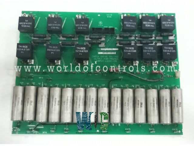
SPECIFICATIONS
Part Number: DS200PCCAG1ABB
Manufacturer: General Electric
Series: EX2000
Product Type: Power Connect Card
Operating Temperature: 0 to 60oC (32 to 149 oF)
Availability: In Stock
Country of Manufacturer: United States (USA)
Functional Description
DS200PCCAG1ABB is a Power Connect Card developed by General Electric. It is a part of EX2000 excitation system. It serves as a vital link between the control circuitry of the drive and the SCR power bridge, facilitating efficient power transmission and control. The primary function of the board is to establish a seamless interface between the control circuitry of the drive system and the SCR power bridge. This interface enables effective communication and coordination between the control signals generated by the drive's microprocessor and the power switching elements within the SCR bridge.
Features
- Utilization of Pulse Transformers for Gate Drive: Employs pulse transformers to provide gate drive signals to the SCR bridge. These pulse transformers play a crucial role in delivering precise and controlled signals to the gate terminals of the SCRs, ensuring accurate switching and regulation of power flow within the system.
- Inclusion of Snubber Circuits for Low-to-Medium Horsepower Controllers: For low-to-medium horsepower controllers, the board incorporates snubber circuits designed to mitigate voltage spikes across various components of the system. These snubber circuits help control transient voltage fluctuations across the AC lines, DC bus, and gate drivers, enhancing the reliability and stability of the overall system.
- Customization for Higher Horsepower Controllers: In the case of higher horsepower controllers, the board may omit some or all of the snubber circuits. Instead, these snubber circuits may be located elsewhere in the system, allowing for a more tailored approach to voltage spike suppression based on the specific requirements and characteristics of the higher power applications.
- Optimized Power Transmission and Control: By serving as an intermediary between the control circuitry and the SCR power bridge, the board ensures optimized power transmission and control within the drive system. Its use of pulse transformers and snubber circuits contributes to improved efficiency, reliability, and performance, particularly in applications with varying horsepower requirements.
Configurable Jumpers
- JP1 and JP2: Jumpers JP1 and JP2 are essential for establishing connections between specific stab terminals (designated P3 through P10) on the board. The selection of stab terminals depends on factors such as the card group number and system voltage. Proper connection of JP1 and JP2 ensures the correct routing of signals and power within the PCCA board, facilitating optimal performance and compatibility with the system configuration.
- WP3 and WP4: WP3 and WP4 jumpers are used to connect stab terminals P2A to P2B and P1A to P1B, respectively. These jumpers play a crucial role in selecting whether the PCCA snubber capacitors are connected to the same point on the power bridge as the voltage feedback channel. By configuring WP3 and WP4 jumpers appropriately, users can adjust the connection scheme of the snubber capacitors, optimizing their effectiveness in mitigating voltage spikes and enhancing the overall stability of the system.
- Configuration for Different Board Group Numbers and System Voltages: The placement and configuration of wire jumpers vary based on the specific board group number and system voltage requirements.
WOC has the largest stock of Speedtronic control spares. Please contact our staff by phone or email for pricing and availability on any parts and repairs
FREQUENTLY ASKED QUESTIONS
What is DS200PCCAG1ABB?
It is a Power Connect Card developed by General Electrics.
What is the purpose of the jumpers JP1, JP2, WP3, and WP4?
These jumpers serve to establish connections between specific stab terminals, determining the routing of signals and power, as well as the configuration of snubber capacitors.
How do jumpers JP1 and JP2 affect the operation of the board?
JP1 and JP2 must be connected to the appropriate stab terminals (P3 through P10) based on factors such as the card group number and system voltage. This ensures proper signal and power distribution within the board.
What is the role of jumpers WP3 and WP4 in the configuration of the board?
WP3 and WP4 determine whether snubber capacitors are connected to the same point on the power bridge as the voltage feedback channel. Configuring these jumpers correctly optimizes the effectiveness of the snubber capacitors in mitigating voltage spikes.
