SPECIFICATIONS
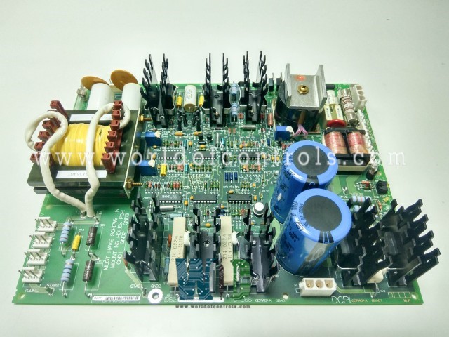
Part Number: DS200GDPAG1ALF
Manufacturer: General Electric
Series: EX2000
Product Type: High Frequency Power Supply Board
Temperature 0 to 60oC (32 to 149 oF)
Availability: In Stock
Country of Manufacturer: United States (USA)
Functional Description
DS200GDPAG1ALF is a High Frequency Power Supply Board developed by General Electric. It is a part of EX2000 excitation system. The High Frequency Power Supply Board boast a power output ranging from 600 to 700 watts (W). Possesses the capability to draw input power from both alternating current (AC) and direct current (DC) sources, ensuring adaptability to diverse operational environments and requirements.
Key Components and Functions
- Input Rectifier and Filter: The board features an input rectifier and filter mechanism, responsible for converting and filtering incoming power from external sources. This process ensures the delivery of clean and stable power to subsequent stages of the power supply system.
- Regulator (Buck Chopper): A regulator, commonly known as a buck chopper, drives a regulated direct current (DC) bus, maintaining a consistent voltage level to meet the demands of connected loads.
27 kHz Inverter: Operating from the regulated DC bus, a 27 kHz inverter is integrated into the GDPA board, facilitating the conversion of DC power into high-frequency alternating current (AC). This inverter plays a pivotal role in powering specific components or systems requiring AC power.
- Output Transformer: The board incorporates an output transformer designed to provide 50 volts AC outputs, catering to the diverse voltage requirements of connected devices or subsystems.
120 V DC Power Supply: Additionally, the board includes a 120-volt DC power supply, ensuring the availability of stable DC power for various applications within the system.
- Control Power Supply: To support the operation of control systems and associated components, the board features a dedicated control power supply, delivering the necessary power to ensure optimal functionality.
- Control Signal Level Circuits: Integrated control signal level circuits enable the processing and manipulation of control signals, facilitating precise control and coordination of system operations.
- Protective Circuits: Critical to the safeguarding of the board and connected equipment, protective circuits are implemented to detect and mitigate potential faults or abnormal operating conditions, ensuring the integrity and reliability of the power supply system.
LED Indicators
- PWR IN (CR1 and CR2): These LED indicators illuminate to signify the presence of power input from external sources. When activated, they indicate that the board is receiving power input, providing a visual confirmation of the power supply status.
- READY (CR37 and CR39): The READY LED indicators serve as indicators of the operational readiness of the board. When illuminated, they indicate that the board has completed its initialization process and is ready for operation. This visual cue assures operators that the board is prepared to perform its intended functions.
- 120 V DC FUSE (N2): The neon indicator labeled 120 V DC FUSE provides visual feedback on the status of the fuse associated with the 120-volt DC power supply. When illuminated, it indicates the integrity of the fuse, providing assurance that the power supply protection mechanism is functioning properly.
- HI VOLT SHORT (N1): The HI VOLT SHORT neon indicator serves as a warning indicator for high-voltage short circuits within the system. When activated, it alerts operators to the presence of a potential short circuit condition, prompting immediate attention and troubleshooting to prevent damage to the board and connected equipment.
Application Data
- Plug and Stab-on Connectors: The High Frequency Power Supply Board offers versatile connectivity options through the inclusion of twelve plug connectors and two stab-on connectors. These connectors serve as interfaces for connecting external devices or subsystems to the board, facilitating seamless integration and compatibility with various system configurations.
- Grounding Mechanism: Ensuring proper grounding is essential for the safe and reliable operation of the board. To achieve this, the board is grounded via three mounting screws, designated as GND1, GND2, and GND3. This grounding mechanism effectively dissipates excess electrical charge and mitigates the risk of electrical hazards, promoting system safety and stability.
- Fuses: Integrated fuses serve as crucial protective devices, safeguarding the board and connected equipment against overcurrent conditions or electrical faults. These fuses help prevent damage to components and ensure the longevity of the board's operation.
- Test Points: Test points are provided to facilitate diagnostic procedures and troubleshooting activities. These points allow for convenient access to key electrical signals and voltages, enabling operators to perform precise measurements and assessments of the board's performance.
WOC has the largest stock of Speedtronic control spares. Please contact our staff by phone or email for pricing and availability on any parts and repairs
FREQUENTLY ASKED QUESTIONS
What is DS200GDPAG1ALF?
It is a High Frequency Power Supply Board developed by General Electrics.
What are the plug and stab-on connectors used for on the board?
The plug and stab-on connectors serve as interfaces for connecting external devices or subsystems to the board, facilitating seamless integration and compatibility with various system configurations.
How is the board grounded?
It is grounded via three mounting screws, designated as GND1, GND2, and GND3. This grounding mechanism effectively dissipates excess electrical charge and promotes system safety and stability.
What is the purpose of the fuses on the board?
The fuses serve as protective devices, safeguarding the board and connected equipment against overcurrent conditions or electrical faults. They help prevent damage to components and ensure the longevity of the board's operation.
How do test points assist in troubleshooting on the board?
Test points provide convenient access to key electrical signals and voltages, enabling operators to perform precise measurements and assessments of the board's performance. They facilitate diagnostic procedures and troubleshooting activities.
