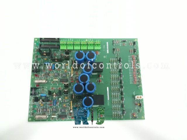
SPECIFICATIONS
Part No.: DS200EXDEG1AEA
Manufacturer: General Electric
Country of Manufacture: United States of America (USA)
Technology: Surface-mount
Temperature Operating: -30 to 65oC
Product Type: De-Excitation Control Board
Availability: In Stock
Series: EX2000
Functional Description
DS200EXDEG1AEA is a de-excitation control board developed by GE. It is a part of EX2000 excitation system. The core functionality of the board revolves around its thyristor and gate control logic. These components are responsible for initiating the firing sequence of the SCR, ensuring precise control and regulation of current flow within the system. The SCR is triggered to fire under specific conditions. This includes when either of the two control inputs is true, indicating the need for current regulation, or when the anode-to-cathode voltage of the SCR surpasses a predetermined break-over voltage threshold.
SCR firing voltage
- The SCR firing voltage plays a crucial role in the operation of the EXDE board, which controls the firing of Silicon-Controlled Rectifiers (SCRs) in electrical systems. This voltage is determined through the configuration of break-over diodes (BODs) and current limiting resistors, facilitated by wire jumpers. The BODs, arranged in series, fire when the voltage from the SCR's anode to cathode exceeds a set threshold, facilitating SCR firing.
- The selection of specific BODs, done through wire jumpers, allows operators to adjust the break-over voltage of the SCR to meet the system's requirements precisely. Additionally, current limiting resistors are employed to regulate the gate current flowing into the SCR, ensuring safe and reliable operation.
- Proper selection and configuration of these components are essential for maintaining the integrity of the SCR firing process and preventing damage or malfunction. By tailoring the SCR firing voltage to match system requirements, operators can optimize performance, efficiency, and reliability, ensuring smooth operation and longevity of electrical systems.
Conduction sensor and Interface
- The Conduction Sensor Board, an integral component of the De-Excitation Module, serves the vital function of providing current flow sensing input to the EXDE board. Within this board are two Hall Effect sensors per sensor circuit, each responsible for detecting magnetic flux and outputting a digital signal.
- Positioned strategically, one sensor detects flux in one direction, while the other senses flux in the opposite direction. These sensors' outputs within each circuit are diode-connected, ensuring efficient signal transmission. Connector JCX facilitates power supply (12 V DC) from the board to conduction sensor 1 and transmits an input signal back to control circuit 1. Similarly, connector JCY serves conduction sensor 2 and control circuit 2. A low output voltage (near 0 V DC) indicates the presence of flux, while a high output voltage (near 12 V DC) signifies the absence of flux.
- Red LEDs are incorporated into both the Conduction Sensor Board and the board to provide visual indication when current flow is detected. On the Conduction Sensor Board, there are two LEDs per sensor circuit, totaling four LEDs, while the board hosts one LED per control circuit, totaling two LEDs. These LEDs illuminate whenever current flow is detected, providing immediate visual feedback on system operation. To ascertain if current flow has been detected, voltage measurement from 3TB-2 to 3TB-1 (for control circuit 1) or from 6TB-2 to 6TB-1 (for control circuit 2) can be performed. These measurements provide insight into the presence or absence of current flow, aiding in system monitoring and diagnostics.
- The voltage supply for the conduction sensors can be sourced either internally or externally, offering flexibility in system configuration. This capability is governed by Berg jumper settings, allowing operators to select the most suitable voltage supply option based on system requirements and operational preferences. Overall, the Conduction Sensor Board and its interface components play a pivotal role in current flow sensing, contributing to the efficient and reliable operation of the De-Excitation Module and the broader electrical system.
The WOC team is always available to help you with your EX2000 requirements. For more information, please contact WOC.
Frequently Asked Questions
What is DS200EXDEG1AEA?
It is a de-excitation control board developed by GE under the EX2000 series.
How many control circuits are available on the board, and what are their purposes?
The board features two separate control circuits: control circuit 1 and control circuit 2. Each circuit serves distinct functions within the De-Excitation Module, facilitating precise control and regulation of the silicon-controlled rectifiers (SCRs) and associated components.
What are the connections for control circuits 1 and 2 on the board?
Each control circuit is equipped with three terminal boards for connections, providing designated points for interfacing with external components and systems. These connections are essential for integrating the board into the broader electrical system and ensuring proper communication and functionality.
How is the firing control signal generated for the SCRs in control circuits 1 and 2?
The firing control signal, also known as the firing pulse, is generated by applying 24 V DC from specific terminal boards to designated points for control circuit 1 and control circuit 2. Specifically, 24 V DC is applied from 1TB-2 to 1TB-1 for control circuit 1 and from 4TB-2 to 4TB-1 for control circuit 2, initiating the SCR firing sequence.
