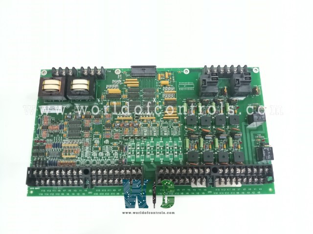
World Of Controls understands the criticality of your requirement and works towards reducing the lead time as much as possible.
DS200DDTBG2ABB - LCI Auxiliary I/O Terminal Board is available in stock which ships the same day.
DS200DDTBG2ABB - LCI Auxiliary I/O Terminal Board comes in UNUSED as well as REBUILT condition.
To avail our best deals for DS200DDTBG2ABB - LCI Auxiliary I/O Terminal Board, contact us and we will get back to you within 24 hours.
SPECIFICATIONS:
Part Number: DS200DDTBG2ABB
Manufacturer: General Electric
Series: Mark V LM
Product Type: LCI Auxiliary I/O Terminal Board
Number of channels: 12
Power supply voltage: 28 V dc
Voltage Range: 14 to 32 V dc
Operating temperature: -30 to 65°C
Availability: In Stock
Country of Origin: United States
Manual: GEI-100219
FUNCTIONAL DESCRIPTION:
DS200DDTBG2ABB is an LCI Auxiliary I/O Terminal Board manufactured and designed by General Electric as part of the Mark V LM Series used in GE Speedtronic Gas Turbine Control Systems. The DS200DDTB board (DDTB) is a high-voltage terminal board for system connections of auxiliary I/O signals. The board connects to a DS200ADMA (ADMA) analog-to-digital module daughterboard mounted on a DS200DSPC (DSPC) digital signal processor control board. High-density connectors and a ribbon cable connect the DDTB to the ADMA board. The ADMA board provides power for the DDTB. The DDTB provides signal conditioning, scaling, buffering, and isolation to make the harsh environment system-level signals accessible to the DSPC board’s digital signal processor (DSP). External wiring connections from high voltage signals, contact I/O, current measurement (via low-level Hall-effect devices), or high-current CTs can be connected to the DDTB terminals. There are G1 and G2 versions of the DDTB board. The G2 lacks some of the functionality of the G1 and is noted where applicable.
ANALOG INPUTS:
HIGH-VOLTAGE AC INPUTS: There are two isolated inputs for connection to high-voltage ac signals. These use a step-down transformer, passive filtering, and a buffer to provide a ±5 V peak-to-peak signal to the ADMA board’s VCO inputs (at 693 V rms applied). These inputs have a separate screw terminal block rated and isolated for 1000 V peak transients.
HIGH-CURRENT SIGNAL INPUTS: Six inputs with current sensing resistors are suitable for ±5 amp continuous current signals (intended for CT inputs). These are buffered differentially and can tolerate ±12 V of common mode voltage. Each input is filtered and scaled. These inputs have a screw-type terminal block and are protected from voltage surges.
LOW CURRENT SIGNAL INPUTS: There are three inputs with current sensing resistors suitable for ±0.224 amp continuous current signals (intended for LEM current transducer signals). These are buffered differentially and can tolerate ±12 V of common mode voltage. Each input is filtered and scaled. These inputs have a screw-type terminal block and are protected from voltage surges.
ANALOG OUTPUTS:
VOLTAGE OUTPUTS: There are four buffered analog outputs available at screw terminals. These include a gain of two to provide a ±10 V output range from the ±5 V range output signal from the ADMA board. Each output has a 200-ohm series resistor to isolate the amplifier from the customer connection.
4-20 mA CURRENT OUTPUTS: Two of the analog outputs also drive current source output buffers to provide support for the 4-20 mA current loop output signals. Both the voltage and current outputs are active at all times and can be used individually or together by wiring to their respective output terminals. There is an inversion and gain stage in the 4-20 mA driver such that a +5 V input from the ADMA board causes the output to produce 4 mA and a −5 V input causes the output to produce 20 mA.
WOC has the largest stock of GE Speedtronic Control System Replacement Parts. We can also supply unused and rebuilt backed-up with a warranty. Our team of experts is available round the clock to support your OEM needs. Our team of experts at WOC is happy to assist you with any of your automation requirements. For pricing and availability on parts and repairs, kindly contact our team by phone or email.
What are the main functions of an LCI Auxiliary I/O Terminal Board?
The primary function is to expand the capacity for connecting low-current devices such as sensors, switches, indicators, or other control components to a central control system. It acts as an interface between these devices and the main control unit.
How does an LCI Auxiliary I/O Terminal Board differ from other interface boards?
Unlike traditional interface boards, the LCI Auxiliary I/O Terminal Board is specifically designed for low-current applications. It typically features specialized circuitry and components optimized for handling signals with lower power requirements.
What types of devices can be connected to an LCI Auxiliary I/O Terminal Board?
Various types of low-current devices can be connected, including proximity sensors, limit switches, push buttons, indicator lights, and similar components commonly found in industrial automation and control systems.