SPECIFICATIONS
Part Number: DS200DCFBG1BKC
Manufacturer: General Electric
Series: Drive Control
Product type: Power Supply Board
Availability: In Stock
Country of Manufacture: United States (USA)
Functional Description
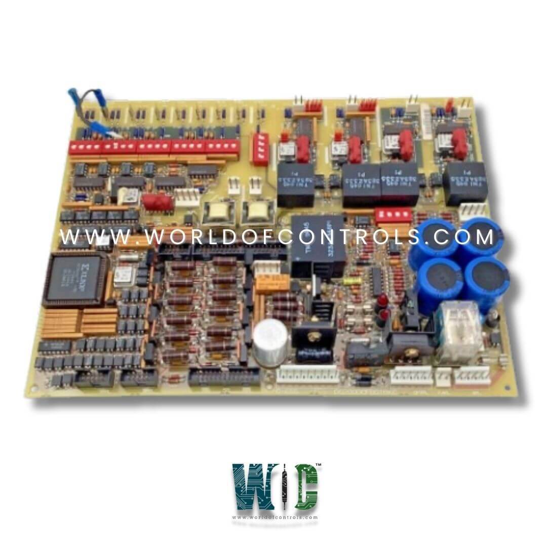
DS200DCFBG1BKC is a Power Supply Board designed and developed by GE. It is a part of Drive Control series. DCFB plays a crucial role in converting and regulating incoming power to various output voltages required for the operation of the control system. The board receives 38 VAC from the Control Power Transformer (CPT) and 24 VDC. This input voltage is utilized as the primary power source for generating regulated DC outputs.
Features
- Full-Wave Rectification and Filtering: The incoming AC voltage is subjected to full-wave rectification and filtering processes to produce unregulated 24 VDC outputs. These outputs serve as the primary power sources for the board's internal circuitry and for powering external components.
- Output Ratings: The +24 VDC output is rated at 3 A, while the -24 VDC output is rated at 1 A, providing sufficient power for various components within the control system. Regulators on the board derive 15 VDC outputs from the 24 VDC supplies. Each 15 VDC output is rated at 0.8 A, with 0.25 A available for external loading.
- +5 VDC Output and Regulation Monitoring: The board generates a regulated +5 VDC output from the +24 VDC supply, rated at 4 A. A /PSEN signal on 2PL indicates the status of the +5 VDC supply; it goes low when the supply is in regulation and high when it goes out of regulation. This signal is crucial for generating a microprocessor reset on the Drive Control Card (SDCC/LDCC) if the +5 VDC supply deviates from its specified range.
- Isolated Power Supplies: It provides isolated +5 VDC and 15 VDC supplies to power the armature current feedback circuits, ensuring accurate measurement and control of motor parameters.
- Short Circuit Protection: The power supply outputs are protected against short circuits by fuses FU2 and FU3 (7 A, 2AG). Blown fuse indication is provided by LEDs CR51 and CR55. Additionally, the 115 VAC output is protected by fuse FU1 (1/2 A, 2AG), with blown fuse indication provided by neon light LT1.
AC Line Current Transformer Interface
- In certain applications, AC line current transformers (ACCTs) are utilized to measure the currents flowing through the drive's AC input lines, particularly L1 and L3. These ACCTs provide crucial data for monitoring and control purposes.
- Switch SW7 on the board is dedicated to selecting the burden resistance, which is determined based on the rate 1 per unit (pu) DC output current. The rated 1 pu DC output current is defined as 0.5 V across the DCFB board's ACCT burden resistors.
By adjusting SW7, users can configure the burden resistance to match the specific requirements of the application and ensure accurate measurement of line currents.
- The board processes the signals from the ACCTs and sends them to the Drive Control Card (SDCC/LDCC) board through connection 1PL. These signals contain valuable information about line currents, which are utilized by the SDCC/LDCC board for various monitoring and protection functions.
- The SDCC/LDCC board utilizes the ACCT signals from the DCFB board to monitor for commutation failure and AC instantaneous overcurrent (IOC) events. These checks are essential for ensuring the stability and safety of the drive system operation.
- The board may feature a dedicated test point labeled as ACCT, which allows users to directly view the ACCT signals. This test point facilitates diagnostic and troubleshooting activities, enabling users to monitor the performance of the ACCTs and ensure proper functionality.
WOC is happy to assist you with any of your GE requirements. Please contact us by phone or email for pricing and availability on any parts and repairs.
FREQUENTLY ASKED QUESTIONS
What is DS200DCFBG1BKC?
It is a Power Supply Board designed and developed by GE
What is the function of switch SW7 on the board?
Switch SW7 is used to select the burden resistance, which is crucial for accurate measurement of line currents based on the rated 1 per unit (pu) DC output current.
What monitoring functions are performed by the SDCC/LDCC board using ACCT signals?
The SDCC/LDCC board monitors for commutation failure and AC instantaneous overcurrent (IOC) events using the ACCT signals received from the board.
How can users view ACCT signals for diagnostic purposes?
The board may feature a dedicated test point labeled as ACCT, allowing users to directly view the ACCT signals. This facilitates diagnostic and troubleshooting activities.
