SPECIFICATIONS
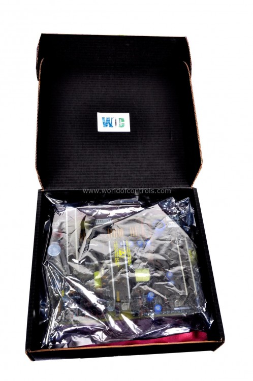
Part Number: DS200DCFBG1AAA
Manufacturer: General Electric
Series: EX2000
Product type: Power Supply Board
Availability: In Stock
Country of Manufacture: United States (USA)
Functional Description
DS200DCFBG1AAA is a Power Supply Board designed and developed by GE. It is a part of EX2000 control system. Power Supply Board is responsible for managing power distribution and ensuring reliable operation of various subsystems. It receives power input from the control power transformer (CPT), typically in the form of 38 VAC and 115 VAC (or 24 VDC). These input voltages are essential for powering up the board and its associated components.
Features
- Power Distribution: Upon receiving the input power, the board distributes control-level power to different sections of the drive system. This power is crucial for the operation of control circuits, processors, and other electronic components within the system.
- Enclosure Fan Power: In addition to providing control-level power, also supplies 115 VAC power (or NA) specifically to the enclosure fans. These fans play a crucial role in maintaining optimal operating temperatures within the drive enclosure by facilitating air circulation and heat dissipation.
- Transformer Interface: Interfaces with the control power transformer (CPT) to regulate and manage the incoming power supply. It ensures that the power supplied to the drive system and enclosure fans is within the specified voltage and current limits, preventing damage to sensitive components.
- Power Regulation and Protection: Incorporates power regulation and protection mechanisms to safeguard against voltage spikes, surges, and fluctuations in the input power supply. These protections help maintain system stability and reliability, preventing potential damage to the drive system and associated components.
- Redundancy and Fault Tolerance: In mission-critical applications, redundant boards may be employed to ensure continuous operation and fault tolerance. Redundancy mechanisms allow for seamless switchover to backup power supplies in the event of a failure, minimizing downtime and ensuring uninterrupted system performance.
- System Integration: Seamlessly integrates with the overall control architecture of the system, working in conjunction with other components such as processors, communication modules, and input/output devices. This integration ensures coordinated operation and efficient power management across the entire system.
Voltage Attenuation
- Analog Representation of Motor Voltage: The motor voltage attenuation circuit is designed to provide an analog representation of the motor voltage. It converts the raw voltage signal from the motor into a scaled analog voltage output that accurately reflects the motor's operating voltage.
- Signal Transmission to SDCC/LDCC Board: The analog voltage signal generated by the attenuation circuit is transmitted to the SDCC/LDCC (Speed Control and Data Collection/Load Control and Data Collection) board through the 1PL-6 connection. This allows the SDCC/LDCC board to monitor and analyze the motor voltage for various control and diagnostic purposes.
- Biasing at 2.5 V: The attenuation circuit is biased at a reference voltage of 2.5 V. This biasing ensures that the output voltage signal remains centered around the mid-point of the voltage range (0 to 5 V), providing symmetrical voltage variation for both positive and negative motor voltage deviations.
Configurable Jumpers (JP)
- The boards typically include 12 configurable jumpers, with some revisions featuring 13 jumpers (e.g., revision BKC and later boards). These jumpers serve as physical connections that can be opened or closed to enable or disable specific functions or features on the board.
- Most of the jumper settings are factory-set, with the positions documented in the test data sheets provided with each controller. These factory settings ensure that the board operates according to the intended specifications and requirements.
- When replacing a DCFB board, it's crucial to set the jumpers on the new board in the same positions as those on the board being replaced, unless otherwise instructed. This ensures consistency in the configuration and functionality of the control system.
Dual In-line Package (DIP) Switches (SW)
- In addition to jumpers, DCFB boards also feature seven DIP switches. DIP switches are small switches packaged in a dual in-line configuration, allowing users to toggle individual switches on or off to modify the board's settings.
- Similar to jumpers, most of the DIP switch settings are factory-configured, and the factory-set positions are documented in the test data sheets provided with each controller. These settings determine specific parameters or configurations of the board.
- When replacing a DCFB board, it's essential to set the DIP switches on the new board according to the positions on the board being replaced, unless explicit instructions state otherwise. This ensures consistency and compatibility with the existing control system setup.
WOC is happy to assist you with any of your GE requirements. Please contact us by phone or email for pricing and availability on any parts and repairs.
FREQUENTLY ASKED QUESTIONS
What is DS200DCFBG1AAA?
It is a Power Supply Board designed and developed by GE
How are the factory settings of jumpers and DIP switches determined?
The factory settings of jumpers and DIP switches are determined during the manufacturing process based on the intended specifications and requirements of the control system. These settings are documented in the test data sheets provided with each controller.
Why is it important to set jumpers and DIP switches consistently during replacement?
Consistent setting of jumpers and DIP switches ensures compatibility and proper operation within the control system setup. Inconsistent configurations may lead to functional errors, compatibility issues, or improper system behavior.
What should I do if I need to replace a board?
When replacing a board, it's essential to set the jumpers and DIP switches on the new board in the same positions as those on the board being replaced, unless explicit instructions state otherwise. This ensures consistency and compatibility with the existing control system setup.
