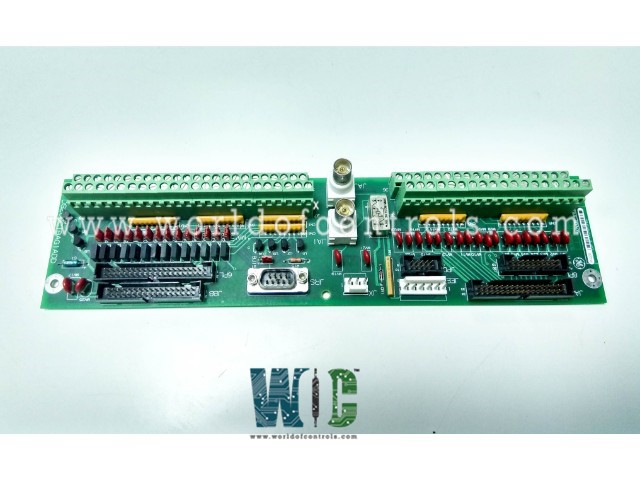
DS200CTBAG1AAB - Analog Termination Board

DS200CTBAG1AAB - Analog Termination Board DS200CTBAG1AAB - Analog Termination Board

World Of Controls understands the criticality of your requirement and works towards reducing the lead time as much as possible.

DS200CTBAG1AAB - Analog Termination Board is available in stock which ships the same day.

DS200CTBAG1AAB - Analog Termination Board comes in UNUSED as well as REBUILT condition.

To avail our best deals for DS200CTBAG1AAB - Analog Termination Board, contact us and we will get back to you within 24 hours.

SPECIFICATIONS

Part No.: DS200CTBAG1AAB
Manufacturer: General Electric
Country of Manufacture: United States of America (USA)
Temperature: -30 to + 65oC
Product Type: Analog Termination Board
Availability: In Stock
Series: Mark V

Functional Description

DS200CTBAG1AAB is an analog termination board developed by GE. It is a part of Mark V control system. Analog Termination Module is located in the R5 core of the system. It serves as a central hub for various analog signals and connections, facilitating communication between different parts of the control system. The module is responsible for monitoring the power source from the Mark V LM system. This connection, originating from the TCPD board in PD, ensures that the CTBA module has access to vital power information, enabling it to operate effectively and reliably. A bypass relay is integrated into the module to ensure continued communication via the COREBUS even in the event of power loss to the CTBA. This redundancy mechanism enhances the resilience of the system, ensuring that critical communication pathways remain operational during unexpected power disruptions.

Terminal Board Connections

  • 4.20 mA Output: This connection allows for the output of 4-20 mA signals, commonly used for transmitting process control signals to external devices or systems.
  • 4.20 mA Input: The 4-20 mA input connection enables the CTBA module to receive signals from sensors or devices, providing valuable data for monitoring and control purposes.
  • Shaft Voltage and Shaft Current Connections: These connections are crucial for monitoring the voltage and current of shafts within the system, providing insights into the operational status and health of rotating machinery.
  • IONET Connection to STCA Board: The IONET connection links the module to the STCA board, facilitating communication and data exchange between these components.
  • COREBUS Connection to QTBA Board: The COREBUS connection allows communication with the QTBA board located in R1, enabling seamless data transfer and coordination between different cores of the control system.

Connections

  • The 8PL connector carries the IONET signals to the STCA board located in the R5 core. This connection enables communication between the CTBA module and the STCA board, allowing for the exchange of data and control signals.
  • Connector JAA is utilized to carry the 4.20 mA outputs from the TCCA board in the R5 core. These outputs are transmitted to external devices or systems, providing control signals or data for monitoring purposes.
  • Connectors JAI and JAJ are designated for the COREBUS connection. If these connectors are not used, termination resistors should be attached to ensure proper signal termination and integrity within the COREBUS network.
  • The JBB connector carries 4.20 mA inputs, as well as shaft voltage and current signals, to the TCCA board in the R5 core. This connection allows the TCCA board to receive input signals for processing and analysis, including data related to shaft conditions and operation.
  • Connector JEE communicates the COREBUS signals with the STCA board in the R5 core. This connection ensures seamless data exchange and coordination between the COREBUS network and the STCA board, enabling efficient control and monitoring of the system.
  • The JPD connector carries the 24 V DC power signal from the TCPD board located in the PD core. This power signal provides the necessary power supply to the CTBA module, ensuring its proper operation and functionality.
  • Connector JX communicates the IONET signals with the TCDA board in the Q51 core. This connection enables data exchange between the CTBA module and the TCDA board, facilitating communication and coordination between different cores of the control system.
  • The 6PL connector is typically not used and remains unused in most configurations of the CTBA module.

The WOC team is always available to help you with your Mark V requirements. For more information, please contact WOC.

Frequently Asked Questions

What is DS200CTBAG1AAB?
It is an analog termination board developed by GE under the Mark V series.

What are the functions of connectors BJ1 through BJ14 on the module?
Connectors BJ1 through BJ14 on the module connect the NEG terminal of the respective mA input to DCOM. This configuration ensures proper grounding and signal integrity for each mA input, allowing for accurate measurement and monitoring of analog signals.

How do connectors BJ1 through BJ14 contribute to signal processing in the module?
Connectors BJ1 through BJ14 establish the electrical connection between the NEG terminal of each mA input and DCOM. By grounding the NEG terminal, these connectors help minimize noise and interference, ensuring reliable and accurate signal processing within the module.

What is the purpose of connector BJ15 on the module?
Connector BJ15 on the CTBA module connects the RS232 Monitor Port (TIMN) to DCOM. This connection allows for communication with the RS232 Monitor Port, facilitating monitoring and diagnostic activities. By linking the RS232 Monitor Port to DCOM, users can access and analyze data transmitted through the port effectively.