SPECIFICATIONS
Part No.: IS200UCVEH2AE
Manufacturer: General Electric
Country of Manufacture: United States of America (USA)
Size: 7.0 in x 13.0 in
Microprocessor: Intel Celeron 300 MHz
Operating System: QNX
Product Type: Controller Module
Availability: In Stock
Series: Mark VI
Functional Description
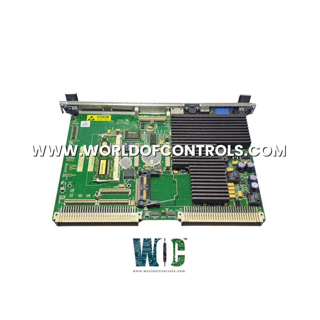
IS200UCVEH2AE is a controller module developed by GE. It is a part of the Mark VI control system. It is designated as the standard Mark VI controller in the system depicted. It operates as a single-slot board, designed to accommodate the demanding requirements of the system. Central to its functionality is a 300 MHz Intel Celeron processor, renowned for its robust performance in computational tasks. This processor serves as the primary computing unit, capable of executing complex control algorithms and managing data processing operations with efficiency and accuracy.
Features
- In terms of memory resources, it is equipped with 16 Mb of flash memory and 32 Mb of DRAM. The flash memory provides storage capacity for firmware, configuration data, and critical system parameters, ensuring persistent access to essential information.
- Meanwhile, the DRAM facilitates dynamic memory allocation for real-time control tasks, data buffering, and temporary storage requirements, enabling responsive and efficient operation of the controller.
- Functionally, the UCVEH2 integrates seamlessly into the system architecture, providing a stable and reliable platform for executing control strategies and coordinating automation processes. Its hardware specifications, coupled with sophisticated software interfaces and real-time operating systems, contribute to its versatility and adaptability in diverse industrial environments.
Board Replacement
Replacing a controller is a meticulous process that demands precision and care to ensure seamless functionality and system integrity. Whether prompted by a failure or as part of routine maintenance, following a structured procedure is paramount to guaranteeing a smooth transition and minimizing downtime. The steps outlined below provide a comprehensive guide for replacing a controller:
- Power Down and Disconnect: As a precautionary measure, power down the rack where the controller resides, and disconnect all cables from the front of the controller board. This ensures safety and prevents any electrical interference during the replacement process.
- Remove and Replace: Carefully remove the failed controller and replace it with a spare controller. Attention to detail is crucial here to avoid damage to the surrounding components and ensure proper seating of the new controller.
- Disconnect VCMI: Extend the VCMI (Visual Control & Monitoring Interface) out of the rack sufficiently to disconnect it from the backplane. This step facilitates direct communication with the controller during the reloading process.
- Connect Serial Loader Cable: Establish a connection between the computer and COM1 of the controller using the serial loader cable.
- Configure TCP/IP Address: Utilize the serial loader to configure the controller with its TCP/IP address, ensuring seamless communication within the network environment.
- Reconnect Ethernet Cable and Power Up: Reconnect the Ethernet cable to the controller and proceed to power up the rack, initiating the boot-up sequence for the new controller.
- Download Runtime: Utilize the designated toolbox to download the runtime to the controller, enabling it to execute essential system functions and processes.
- Download Application Code: Use the toolbox to download the application code to permanent storage within the controller, ensuring persistence and accessibility for future operations.
Ethernet LEDs
- Active LED:
- Blinking: Indicates that the Ethernet interface is actively transmitting or receiving data packets. A blinking Active LED signifies that the interface is operational and engaged in network communication.
- Solid: Indicates that the Ethernet interface is inactive or not transmitting or receiving data packets. A solid Active LED suggests that the interface is not currently engaged in network communication.
- Link LED:
- Yellow: Indicates that the Ethernet interface is operating at a speed of 10BaseT. This speed is associated with older Ethernet standards and offers a maximum data transfer rate of 10 Mbps.
- Green: Indicates that the Ethernet interface is operating at a speed of 100BaseTX. This speed is associated with newer Ethernet standards and offers a maximum data transfer rate of 100 Mbps.
The WOC team is always available to help you with your Mark VI requirements. For more information, please contact WOC.
Frequently Asked Questions
What is IS200UCVEH2AE?
It is a controller module developed by GE under the Mark VI series.
What are the key specifications of the UCVEH2 controller?
It�is a single-slot board featuring a 300 MHz Intel Celeron processor, 16 or 128 MB of flash memory, 32 MB of DRAM, and a single 10BaseT/100BaseTX (RJ-45) Ethernet port for connectivity to the UDH.
How does the UCVEH2 differ from other UCVE controller forms?
While UCVEH2 is the standard Mark VI controller, other forms like UCVEM01 to UCVMEM05 may vary in specifications and intended applications.�
What is the function of the Ethernet port?
The Ethernet port enables connectivity to the Universal Data Highway (UDH), facilitating communication and data exchange within the system or with external devices, crucial for industrial control applications.
