SPECIFICATIONS
Part Number: IS200DAMCG1A
Manufacturer: General Electric
Function: Gate Drive Amplifier board
Series: Drive Control
Frame Rate: 250
Powerrex IGBT: CM400HA-28H
No.of Boards/drive: three
IGBT/phase leg: one
LED: four
Availability: In Stock
Country of Manufacture: United States (USA)
Functional Description
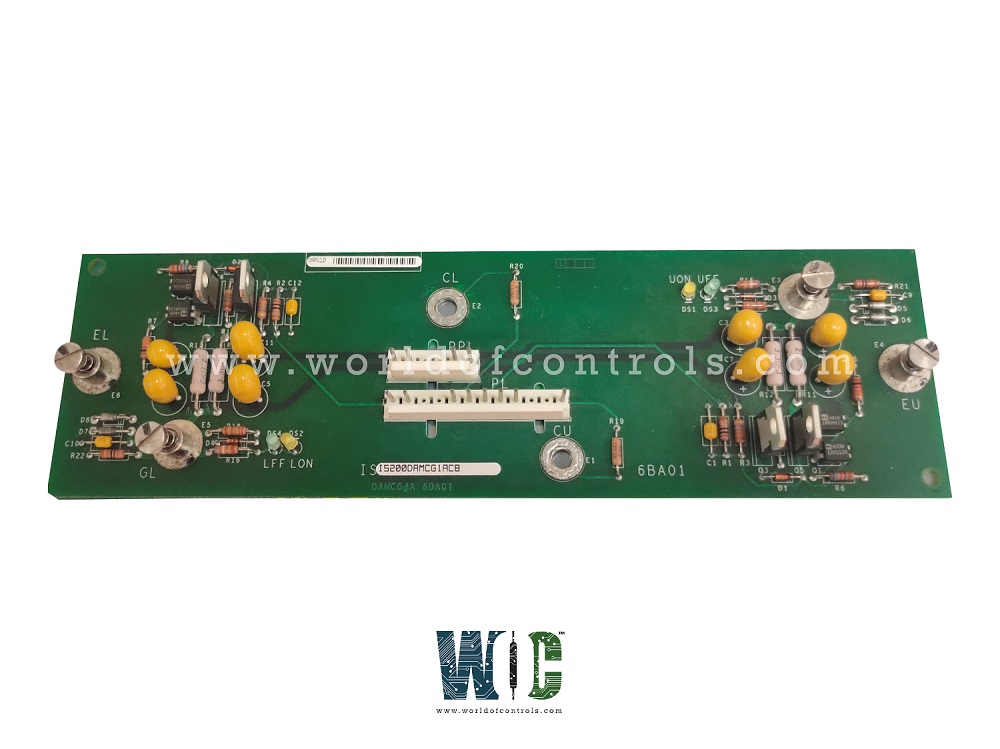
IS200DAMCG1A is a Gate Drive Amplifier board developed by GE. It is a part of GE drive control system. In a low voltage Innovation Series drive, these boards serve as an interface between the devices in charge of switching power (IGBTs) and the control rack. LEDs, or light-emitting diodes, in these devices indicate whether or not the IGBT is turned on. It ensures that the IGBTs are turned on and off correctly by amplifying the gate drive signals that control the IGBTs.
The board also includes LEDs, or light-emitting diodes, which provide a visual indication of the status of the IGBTs. These LEDs indicate whether or not the IGBT is turned on, which can help to diagnose any potential issues with the system. It features one IGBT per phase leg, ensuring that it can handle the power requirements of the system. Additionally, the board includes four LEDs, providing a visual indication of the status of the IGBTs.
IS200DAMCG1A Features
- In a low voltage Innovation Series drive, these boards serve as an interface between the devices in charge of switching power (IGBTs) and the control rack.
LEDs, or light-emitting diodes, in these devices indicate whether or not the IGBT is turned on.
- The DAMC is one of the DAM gate drive board variants. The power rating of the board is 250 frames. This board, along with DAMB and DAMA boards, are in charge of amplifying current in order to provide the final stage of gate drive for a power bridge phase leg. These boards have a +15/-7.5 power supply input.
- The boards are directly connected to the IGBT gate, as well as the collector and emitter terminals. DAMC boards are also linked to the control rack's BPIA Bridge Personality Interface, or BPIA board. The component has four different LEDs or light-emitting diodes. Two of these are yellow, DS1 and DS2. The other two are green, DS3 and DS4. The DS4 and DS2 are located at the bottom of the PCB's left half. These are also identified by the initials LFF and LON. The DS1 and DS3 LEDs are located near the top of the right half of the board and are labeled with the initials UON and UFF.
Product Attributes
- DAMC is a Gate Drive Amplifier board that is designed to interface with the inverter card in an Innovation Series drive. It is responsible for amplifying control signals from the inverter card and transmitting them to the gate drivers in the drive system.
- The board contains six optocouplers for signal isolation and protection, as well as a microprocessor for control and monitoring functions.
- The board is also equipped with fault detection and reporting capabilities to help diagnose and troubleshoot problems in the drive system. It is designed for use in high-power applications, with a voltage rating of up to 690 volts and a current rating of up to 1700 amperes. The board is typically mounted on the front panel of the drive and is connected to the inverter card through a ribbon cable.
Board Replacement Procedure
To remove the board
- Check that the drive where the board is located has been deactivated.
- Open the cabinet door on the drive. Test any electrical circuits before touching them with high-voltage equipment to ensure that power is turned off.
- Find the heatpipe heat exchanger assembly and the IGBTs with mounted directly beneath them.
- Disconnect the cable from the board's connector PL and secure it out of the way.
- Disconnect the cable from the connector PPL and secure it out of the way.
- Remove the two Keps nuts that secure the board. Remove the board from the IGBT stud connections by loosening the four captive fasteners.
To install the new (replacement)
- Place the new board over the IGBT stud connections, then finger-tighten the four captive fasteners and install the two Keps nuts.
- Tighten each Keps nut to 13 inch-pound torque to secure the new board. Then tighten the four captive fasteners completely.
- Reconnect the cable to the new board's connector PPL.
- Reconnect the cable to the new connector PL.
- Check all connections, buses, and bolted hardware for proper installation.
- Examine the drive cabinet visually for any tools, debris, or other hardware that may have been left in the drive.
- Snap the drive cabinet door shut.
WOC has the largest stock of Speedtronic control spares. Please contact our staff by phone or email for pricing and availability on any parts and repairs
FREQUENTLY ASKED QUESTIONS
What is IS200DAMCG1A?
It is an inverter card developed by General Electrics.
What is the power rating of the board?
It is 250 frames.
What is the function of the board in the drive system?
It serves as an interface between the IGBTs and the control rack, amplifying current to switch the power devices on and off.
What LEDs are present on the DAMCG1A?
There are four LEDs on the board, two yellow (DS1 and DS2) and two green (DS3 and DS4).
