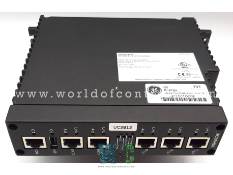
World Of Controls understands the criticality of your requirement and works towards reducing the lead time as much as possible.
IS421UCSBH3A - UCSB Controller Module is available in stock which ships the same day.
IS421UCSBH3A - UCSB Controller Module comes in UNUSED as well as REBUILT condition.
To avail our best deals for IS421UCSBH3A - UCSB Controller Module, contact us and we will get back to you within 24 hours.
SPECIFICATIONS:
Part Number: IS421UCSBH3A
Manufacturer: General Electric
Series: Mark VIeS
Product Type: UCSB Controller Module
Microprocessor: 1200 MHz Intel EP80579
Memory: 256 MB
Operating System: QNX Neutrino
Programming: Boolean
Primary Ethernet Interface: 10Base-TX/100Base-TX
Operating temperature: -30 to 65 °C
Size: 10.16 cm wide x 33.02 cm
Repair: 3-7 Day
Availability: In Stock
Country of Origin: United States
Manual: GEH6721
FUNCTIONAL DESCRIPTION:
IS421UCSBH3A is a UCSB Controller Module manufactured and designed by General Electric as part of the Mark VIeS Series used in GE Distributed Control Systems. The UCSB controllers are stand-alone computers that run the application code. The controller mounts in a panel, and communicates with the I/O packs through on-board 1/0 network (IONet) interfaces. IONet is a private special-purpose Ethernet that only supports Mark controls I/O modules and controllers. The controller operating system (OS) is QNX Neutrino, a real-time, multitasking OS designed for high-speed, high-reliability industrial applications. Unlike traditional controllers where I/O is on a backplane, the UCSB controller does not host any application I/O.
Also, all I/O networks are attached to each controller providing them with all input data. The hardware and software architecture guarantees that no single point of application input is lost if a controller is powered down for maintenance or repair. The Mark VIeS UCSBSIA Safety Controller and Safety 1/0 modules are used for functional safety loops to achieve SIL 2 and 3 capabilities. Mark Vles Safety equipment is used by operators knowledgeable in safety-instrumented system (SIS) applications to reduce risk in critical safety functions. Safety controllers and distributed I/O modules are programmed specifically for safety control use, and this specific control hardware and software has IEC 61508 certification.
INSTALLATION:
The controller is contained in a single module that mounts directly to the panel sheet metal. The following diagrams display the module envelope and mounting dimensions. All dimensions are in inches. The UCSB is to be mounted to the panel as shown with vertical air flow through the fins to be unobstructed.
UCSB SOFTWARE AND COMMUNICATIONS:
The controller is loaded with software specific to its application. It can run rungs or blocks. Minor modifications to the control software may be made online without requiring a restart. The IEEE 1588 protocol is used through the R, S, and T IONets to synchronize the clock of the I/O packs and controllers to within 100 microseconds. External data is transferred to and from the control system database in the controller over the R, S, and T IONets. This includes process I/O to the I/O modules.
WOC has the largest stock of OEM Replacement Parts for GE Distributed Turbine Control Systems. We can also repair your faulty boards and supply unused and rebuilt boards backed up with a warranty. Our team of experts is available round the clock to support your OEM needs. Our team of experts at WOC is happy to assist you with any of your automation requirements. For pricing and availability on parts and repairs, kindly contact our team by phone or email.
What type of power supply does the UCSB Controller Module require?
The UCSB Controller Module typically requires a DC power supply. It may range from 12V to 48V depending on the model. Be sure to consult the datasheet or user manual for the exact power requirements.
What is the input voltage range for the UCSB Controller Module?
Input voltage varies by model but typically falls within a range of 24V DC or 48V DC. Some models may support a wider range. Always check the specifications for the exact voltage limits.
Is the UCSB Controller Module compatible with different types of sensors?
Yes, the UCSB Controller Module is generally compatible with various sensors, including temperature, pressure, flow, and level sensors, depending on the application. The sensors usually communicate with the module via standard industrial protocols like Modbus or analog signals (4-20mA or 0-10V).