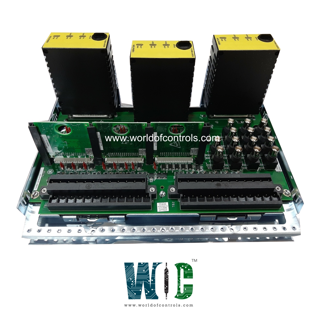
World Of Controls understands the criticality of your requirement and works towards reducing the lead time as much as possible.
IS230TVBAH8A - Vibration Input Assembly Module is available in stock which ships the same day.
IS230TVBAH8A - Vibration Input Assembly Module comes in UNUSED as well as REBUILT condition.
To avail our best deals for IS230TVBAH8A - Vibration Input Assembly Module, contact us and we will get back to you within 24 hours.
SPECIFICATIONS:
Part Number: IS230TVBAH8A
Manufacturer: General Electric
Series: Mark VIe
Product Type: Vibration Input Assembly Module
Number of channels: 8
Number of N24 outputs: 14
N24 maximum current: 12 mA
Number of buffered outputs: 14
Number of channels with selectable pull up of ±28: 8
N28 voltage: 28 normal
N28 maximum current: 400 mA
Voltage Range: 18 - 32 VDC
Mounting: DIN-rail mounting
Technology: Surface mount
Operating temperature: -25 to 65°C
Size: 33.02 cm high x 17.8 cm
Repair: 3-7 Days
Availability: In Stock
Country of Origin: United States
Manual: GEH-6721D
FUNCTIONAL DESCRIPTION:
IS230TVBAH8A is a Vibration Input Assembly Module manufactured and designed by General Electric as part of the Mark VIe Series used in GE Distributed Control Systems. The vibration terminal board (TVBA) acts as a signal interface board for the Mark VIe I/O pack PVIB. In the Mark VI system, the VVIB board works with TVIB. The TVBA provides a direct interface to seismic (velocity), Proximitors, Velomitors, and accelerometer-type probes. The terminal board provides signal suppression and electromagnetic interface (EMI) protection for each input signal. Signals are also connected to a pull-up bias to allow open circuit detection. The signals are passed on to the Mark VIe I/O packs through a 37-pin connector.
The TVBA can be used for either simplex or TMR applications. TMR applications fan the signal to three I/O packs. The TVBA contains buffered outputs to additional connectors beyond the standard 37-pin connection. This feature allows special 9 and 25 pin connectors to feed the Bently Nevada® 3500 monitoring system. A bayonet nut connection (BNC) connection for each channel is also included with this feature to feed other third party monitoring equipment. Mark VIe systems do not use the traditional RKPS power supply. Power is obtained from sourced +28V power supplies, and there is no external source for -28V. The TVBA must maintain the same functionality as the Mark VI TVIB. For this reason, the TVBA will have three removable daughterboards to convert +28 to -28. These boards, WNPS (negative power supply) will be the source for all negative power used by the TVBA.
INSTALLATION:
The TVBA accepts 14 sensor inputs that are wired directly to two I/O terminal blocks. Each block is held down with two screws and has 24 terminals accepting up to #12 AWG wires. A shield termination attachment point is located adjacent to each terminal block.
Input Channels 1 through 8:
Input Channels 9 through 12:
Input Channel 13:
-28V power supply board, WNPS:
OPERATION:
The TVBA supports 14 sensor connections:
BUFFERED OUTPUTS:
Each channel provides additional outputs other than the standard 37-pin connection. The signal output is a buffered version of the monitored signal. Each channel is output on a BNC connector. Each channel is also output through a 25-pin (Vib/Position) or 9-pin (Keyphasor) connector designed to interface with the Bently Nevada 3500 monitoring system. Requirements on the buffers are as follows:
The buffered outputs drive DB25, DB9, and BNC coaxial connectors in parallel. Both the center pin and the shell of the BNC are resistively isolated from the DB connectors. The isolation is sufficient that the DB connector's voltage remains within spec if the BNC connector is shorted.
WOC has the largest stock of OEM Replacement Parts for GE Distributed Control Systems. We can also repair your faulty boards and supply unused and rebuilt boards backed up with a warranty. Our team of experts is available around the clock to support your OEM needs. Our team of experts at WOC is happy to assist you with any of your automation requirements. For pricing and availability on parts and repairs, kindly contact our team by phone or email.
What is the primary function of a Vibration Input Assembly Module?
The Vibration Input Assembly Module is designed to receive and process vibration signals from sensors installed on rotating machinery. These signals typically originate from accelerometers, velocity sensors, or proximity probes.
What type of input signals does the module accept?
This module accepts analog signals such as voltage (e.g., ±5V, 0–10V) or current (e.g., 4–20mA), depending on the sensor type and configuration. Some modules may also support direct sensor connections with integrated signal conditioning for piezoelectric or eddy current-based sensors, enabling accurate acquisition of raw vibration data for further processing.
How does the module ensure the accuracy and reliability of measurements?
To maintain signal integrity, the module often incorporates internal features such as signal filtering (low-pass or band-pass), amplification, and fault diagnostics. Shielded input circuits and isolated channels reduce noise and prevent cross-talk between channels.