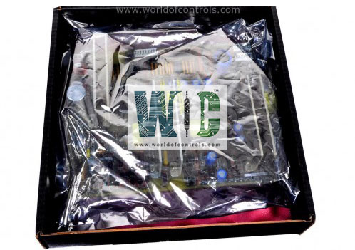
World Of Controls understands the criticality of your requirement and works towards reducing the lead time as much as possible.
IS230TTURH1C - Primary Turbine Protection Input Terminal Board is available in stock which ships the same day.
IS230TTURH1C - Primary Turbine Protection Input Terminal Board comes in UNUSED as well as REBUILT condition.
To avail our best deals for IS230TTURH1C - Primary Turbine Protection Input Terminal Board, contact us and we will get back to you within 24 hours.
SPECIFICATIONS:
Part Number: IS230TTURH1C
Manufacturer: General Electric
Series: Mark VI
Product Type: Primary Turbine Protection Input Terminal Board
Power Supply Voltage: 24 V dc
Shaft Voltage monitor Signal: ± 5 V dc
Shaft Voltage Wiring: Up to 300 m
Shaft Voltage dc Test: 5 V dc
Contact Voltage Sensing: 20 V dc
Mounting: DIN-rail mounting
Technology: Surface mount
Operating temperature: -30° to 65°C
Size: 33.0 cm high x 17.8 cm
Repair: 3-7 Day
Availability: In Stock
Country of Origin: United States
FUNCTIONAL DESCRIPTION:
IS230TTURH1C is a Primary Turbine Protection Input Terminal Board manufactured and designed by General Electric as part of the Mark VI Series used in GE Speedtronic Turbine Control Systems. TTUR has three relays, K25, K25P, and K25A, that all have to close to provide 125 V dc power to close the main breaker 52G. The speed signal cable to VTUR uses the JR5 connector, and the other signals use the JR1 connector. For TMR systems, signals fan out to the JR5, JS5, JT5, JR1, JS1, and JT1 connectors. For the Mark VI system, the VTUR processor works with TTURH1B. Simplex and TMR systems are supported. With TMR systems, TTURH1B is cabled to three VTUR boards. The turbine terminal board, TTUR, works with the turbine I/O processor and has inputs and outputs as follows:
INSTALLATION:
Magnetic pick-ups, shaft pick-ups, potential transformers, and breaker relays are wired to two I/O terminal blocks TB1 and TB2. Each block is held down with two screws and has 24 terminals accepting up to #12 AWG wires. A shield termination strip attached to the chassis ground is located immediately to the left of each terminal block. Jumpers JP1 and JP2 select either SMX or TMR for relay drivers K25 and K25P. TB3 is for optional TTL connections to active speed pickups; these require an external power supply. Simplex systems use cable connectors JR5 and JR1. TMR systems use all six cable connectors.
OPERATION:
In the simplex application, up to four pulse rate signals may be used to measure turbine speed. Generator and bus voltages are brought into TTUR for automatic synchronizing in conjunction with VTUR, the turbine controller, and the excitation system. TTUR has a permissive generator synchronizing relays and controls the main breaker relay coil 52G. In TMR applications all inputs fan to the three control racks. Control signals coming into TTUR from R, S, and T are voted before they actuate permissive relays K25 and K25P. Relay K25A is controlled by the VPRO and TREG boards.
WOC has the largest stock of OEM Replacement Parts for GE Speedtronic Gas Turbine Control Systems. We can also repair your faulty boards and supply unused and rebuilt boards backed up with a warranty. Our team of experts is available round the clock to support your OEM needs. Our team of experts at WOC is happy to assist you with any of your automation requirements. For pricing and availability on parts and repairs, kindly contact our team by phone or email.
What is the function of the Primary Turbine Protection Input Terminal Board?
The Primary Turbine Protection Input Terminal Board serves as a critical interface between turbine protection systems and field devices such as sensors, transducers, and relay outputs. It is responsible for receiving signals from various turbine monitoring instruments, processing them, and transmitting them to the turbine control system for analysis and protective actions.
What types of signals does the Input Terminal Board handle?
The board is designed to handle a variety of signals, including analog and digital inputs from sensors and transducers monitoring parameters such as temperature, pressure, vibration, speed, and overspeed protection.
How does the Input Terminal Board contribute to turbine safety?
This board plays a vital role in turbine safety by continuously monitoring critical operating parameters and relaying this data to the turbine control system. In the event of an anomaly, such as excessive vibration, overspeed, or abnormal temperature fluctuations, the board ensures that the necessary protective actions, such as automatic shutdown or load reduction, are executed promptly.