SPECIFICATIONS
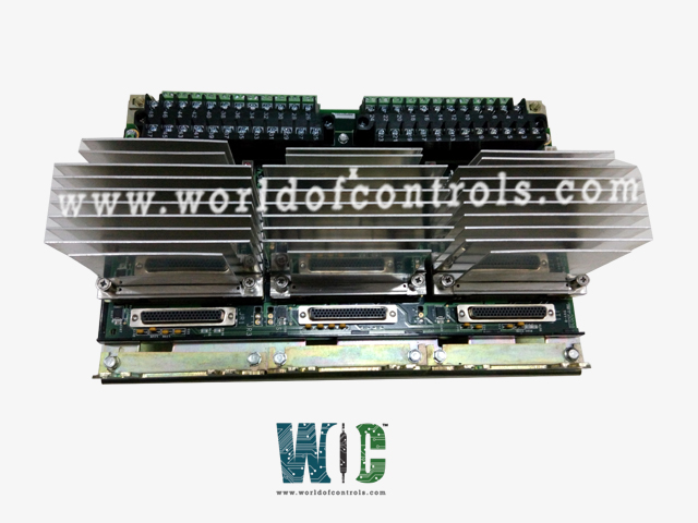
Part No.: IS230TSVC2AG01
Manufacturer: General Electric
Country of Manufacture: United States of America (USA)
Size 33.02 cm high x 17.8 cm wide
Technology: Surface-mount
Temperature Operating: -30 to 65oC
Magnetic PR pickup signal: Generates 150 V p-p into 60 ohm
Active PR pickup signal: Generates 5 to 27 V p-p into 60 ohm
Product Type: The Servo Input/Output Terminal Board
Availability: In Stock
Series: Mark VIe
Functional Description
IS230TSVC2AG01 is a Servo Input/Output Terminal Board developed by GE. It is a part of the Mark VIe control system. The Servo Input/Output (TSVC) terminal board interface with electro-hydraulic servo valves responsible for controlling steam/fuel valves within the system. Terminal board is specifically designed to interface with two electro-hydraulic servo valves, which are instrumental in actuating the steam/fuel valves. These servo valves play a critical role in regulating the flow of steam or fuel within the system.
Features
- Valve Position Measurement: Linear Variable Differential Transformers (LVDTs) are utilized to measure the position of the valves accurately. LVDTs are highly precise sensors capable of converting mechanical motion into electrical signals, providing feedback on valve positions.
- Compatibility with PSVO I/O Pack and WSVO Servo Driver: Tailored to work seamlessly with the PSVO I/O pack and the WSVO servo driver. It is optimized for compatibility with these specific components to ensure efficient operation and performance.
- Support for Simplex, Dual, and TMR Control: Offers support for various control configurations, including simplex, dual, and Triple Modular Redundant (TMR) control setups. This flexibility allows for adaptable system configurations to meet specific operational requirements.
- Power Supply Inputs: Three 28 V DC supplies are routed through plug J28, providing the necessary power for the operation of the servo valves and associated components. These power inputs are essential for ensuring reliable and consistent performance.
- External Trip Connections: Plugs JD1 or JD2 serve as interfaces for external trip signals originating from the protection module. These connections enable the integration of trip signals into the control system, enhancing safety and protection features.
Installation
- Wiring to I/O Terminal Blocks: Sensors and servo valves are directly wired to two I/O terminal blocks. Each block is securely fastened with two screws and features 24 terminals capable of accepting wiring up to 12 AWG. This setup ensures reliable connections between the components and the terminal blocks.
- Shield Terminal Strip: Adjacent to each terminal block, a shield terminal strip is provided, which is connected to chassis ground. This configuration helps to mitigate electromagnetic interference (EMI) and ensures the integrity of signal transmission by providing a grounding point for shielding.
- External Trip Wiring: External trip wiring, which may originate from the protection module, is plugged into either JD1 or JD2 connectors. These connections facilitate the integration of trip signals into the control system, enhancing safety features and system protection.
- TMR Configuration for Servo Outputs: Each servo output can operate in a Triple Modular Redundant (TMR) configuration, providing redundancy for critical operations. The size of each coil current is jumper-selected using JP1, JP3, and JP5 for Servo 1, and JP2, JP4, and JP6 for Servo 2. This allows for customization of the current output based on system requirements.
Fault detection
- Servo Current Out of Limits or Non-Responsive: The board continuously monitors the current flowing through the servo coils. If the current exceeds predefined limits or if the servo does not respond as expected, a fault signal is triggered. This helps prevent damage to the system and ensures proper operation of the servo valves.
- Regulator Feedback Signal Out of Limits: The board also monitors the feedback signals from the regulators, which indicate the position of the servo valves. If these signals fall outside predefined limits, indicating a malfunction or incorrect valve position, a fault signal is generated. This ensures accurate control of the valve positions for optimal system performance.
- Failed ID Chip Detection: The terminal board features an ID chip on its connector, which contains essential information about the board, such as serial number, type, and revision. The system regularly reads this chip to ensure compatibility and proper functioning. If a mismatch or failure is detected during this process, indicating a faulty or incompatible board, a fault signal is generated to alert the operator and prevent potential issues.
The WOC team is always available to help you with your Mark VIe requirements. For more information, please contact WOC.
Frequently Asked Questions
What is IS230TSVC2AG01?
It is a Servo Input/Output Terminal Board developed by GE under the Mark VIe series.
How are servo coils configured in a simplex system?
In a simplex system, servo 1 is configured for the correct coil current using jumper JP1, while servo 2 is configured with jumper JP4.
What configuration is used for servo coils in a TMR system?
In a TMR (triple modular redundant) system, each servo output can have three coils. To configure the coil current for each servo in a TMR system, jumper selections are made using JP1-3 for servo 1 and JP4-6 for servo 2.
What is the purpose of jumper selections on the servo board?
Jumper selections on the servo board determine the coil current configuration for each servo output. These configurations ensure proper operation of the servo valves based on the system redundancy and control requirements.
Are there any other configuration settings that need to be adjusted for the servo board?
Yes, all other servo board configurations, such as tuning parameters and control settings, are typically adjusted using the ToolboxST application. This software allows for comprehensive configuration and optimization of the servo system to meet specific performance and control criteria.
