World Of Controls understands the criticality of your requirement and works towards reducing the lead time as much as possible.
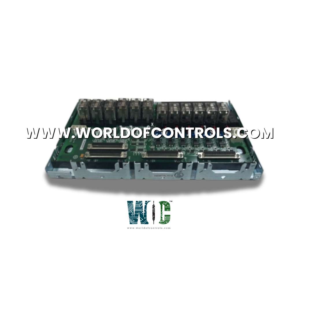
IS230TRLYH1F - TMR Relay Contact Output Terminal Board is available in stock which ships the same day.
IS230TRLYH1F - TMR Relay Contact Output Terminal Board comes in UNUSED as well as REBUILT condition.
To avail our best deals for IS230TRLYH1F - TMR Relay Contact Output Terminal Board, contact us and we will get back to you within 24 hours.
SPECIFICATIONS:
Part Number: IS230TRLYH1F
Manufacturer: General Electric
Series: Mark VIe
Product Type: TMR Relay Contact Output Terminal Board
Number of channels: 12
Maximum operating voltage: 250 V rms
Maximum off-state leakage: 3mA rms
Power supply voltage: 28 V dc
Voltage Range: 14 to 32 V dc
Contact Ratings: 2.25 A at 24 V dc
Max response time on: 1ms
Mounting: DIN-rail mounting
Technology: Surface mount
Storage temperature: -40 to 85°C
Size: 17.8 cm wide x 33.02 cm
Repair: 3-7 Day
Availability: In Stock
Country of Origin: United States
Manual: GEI-100863A
FUNCTIONAL DESCRIPTION:
IS230TRLYH1F is a TMR Relay Contact Output Terminal Board manufactured and designed by General Electric as part of the Mark VIe Series used in GE Distributed Gas Turbine Control Systems. TRLYH1F holds 12 plug-in magnetic relays. The first six relay circuits can be jumpers configured for either dry, Form-C contact outputs, or to drive external solenoids. A standard 125 V dc or 115/230 V ac source, or an optional 24 V dc source, with individual jumper selectable fuses and onboard suppression, can be provided for field solenoid power. The next five relays (7-11) are unpowered isolated Form-C contacts. Output 12 is an isolated Form-C contact, used for special applications such as for ignition transformers. In Mark VIe systems, TRLY is controlled by the VCCC or VCRC board. Cables with molded plugs connect the terminal board to the VME rack where the I/O boards are mounted. Simplex and TMR systems are supported. Plug JA1 is used on simplex systems, and plugs JR1, JS1, and JT1 are used for TMR systems.
The Relay Contact Output module is available in both Simplex and Triple Modular Redundant (TMR) configurations. Users can select the configuration that best addresses their needs for availability and SIL level. This document discusses the TMR Relay Contact Output (TRLY) terminal board and optional daughterboards for contact wetting and fusing, and the Contact Output (TRLY) terminal board. The TRLY terminal board offers TMR capability, but it can also be used in a Simplex configuration using a single YDOA I/O pack. In a TMR I/O configuration, the I/O terminal board performs 2-out-of-3 voting on the discrete outputs.
INSTALLATION:
The 12 relay outputs are wired directly to two I/O terminal blocks mounted on the terminal board as shown in the following figure. Each block is held down with two screws and has 24 terminals accepting up to #12 AWG wires. A shield terminal strip attached to the chassis ground is located on to the left side of each terminal block. Solenoid power for outputs 1-6 is normally plugged to JF1. JF2 can be used to daisy chain power to other TRLYs. Alternatively, customer power may be wired directly into TB3 when power is not plugged into JF1/JF2. JG1 provides power to the customer’s special solenoid, Output 12.
OPERATION:
The TRLYH1F board features solid-state relays, relay drivers, and output monitoring. Upon power-up, the relays remain de-energized until connected to any control source. Each relay output incorporates a failsafe mechanism that triggers de-energization if a cable is unplugged or communication with the associated I/O processor is lost. In simplex operation, control signals and relay output voltage feedback signals pass between the I/O processor and TRLYH1E via connector JA1. For TMR (Triple Modular Redundant) applications, relay control signals are distributed to TRLYH1F from the three I/O processors R, S, and T through connectors JR1, JS1, and JT1. These signals undergo voting, and the resultant signal controls the corresponding relay driver. Power for the relay drivers is supplied from all three I/O processors and is shared through diodes.
WOC has the largest stock of OEM Replacement Parts for GE Distributed Control Systems. We can also repair your faulty boards and supply unused and rebuilt boards backed up with a warranty. Our team of experts is available round the clock to support your OEM needs. Our team of experts at WOC is happy to assist you with any of your automation requirements. For pricing and availability on any parts and repairs, kindly contact our team by phone or email.
What is the function of a TMR Relay Contact Output Terminal Board?
A Triple Modular Redundant (TMR) Relay Contact Output Terminal Board is used in high-reliability systems to ensure fault-tolerant relay contact switching. It operates with three independent relay circuits that use a 2-out-of-3 voting mechanism to maintain safe and continuous operation, even if one relay fails. This type of redundancy is critical in applications like turbine control, safety systems, and industrial automation.
How does the 2-out-of-3 voting logic work in the TMR system?
The board receives the same input signal across three identical relay circuits. The system evaluates the output of all three relays and determines the final state based on majority logic. If at least two relays agree on the output state, the board considers that state valid. This ensures that even if one relay fails or produces an erroneous output, the other two relays maintain correct system operation.
What type of electrical isolation does the board provide?
TMR relay boards use galvanic isolation between input and output to prevent ground loops, transient voltage spikes, and electrical noise from affecting system performance. This isolation ensures reliable operation in industrial environments with high electromagnetic interference (EMI).
{ "@context": "https://schema.org/", "@type": "Product", "name": "IS230TRLYH1F", "image": "https://www.worldofcontrols.com/dynamic_img/product/IS230TRLYH1F.jpg", "description": "IS230TRLYH1F - TMR Relay Contact Output Terminal Board comes in UNUSED and REBUILT condition. Request a Quote for IS230TRLYH1F Now!", "aggregateRating": { "@type": "AggregateRating", "ratingValue": "5", "ratingCount": "36" } }