SPECIFICATIONS
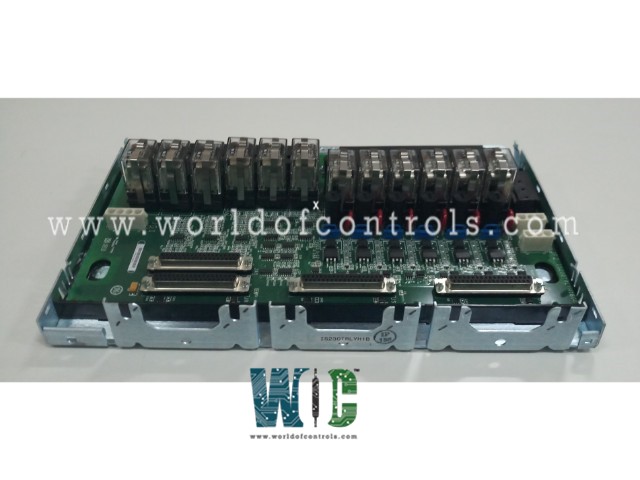
Part No.: IS230TRLYH1B
Manufacturer: General Electric
Country of Manufacture: United States of America (USA)
Technology: Surface-mount
Temperature Operating: -30 to 65oC
Product Type: Relay Output with coil sensing terminal board
Availability: In Stock
Series: Mark VIe
Functional Description
IS230TRLYH1B is a relay output with a coil-sensing terminal board developed by GE. It is a part of Mark VIe control system. The Relay Output with coil sensing (TRLYH1B) terminal board is an integral component in control systems, offering robust and versatile relay management capabilities. This board is equipped with 12 plug-in magnetic relays, each designed to handle specific output configurations tailored to various industrial needs.
Features
- The first six relay circuits on the board are highly customizable and can be configured via jumpers. These circuits can be set up in two primary ways: either as dry, Form-C contact outputs or to drive external solenoids. The dry contact configuration provides a standard method for interfacing with control systems, allowing the relays to operate independently. Alternatively, the relays can be configured to control external solenoids, making them versatile for applications requiring physical actuation.
- To support different operational environments, the board accommodates multiple power source options. It can use a standard 125 V DC or 115/230 V AC power supply. Additionally, there is an option to use a 24 V DC power source, which includes individual jumper-selectable fuses. This setup also features on-board suppression to protect the system against voltage spikes and other electrical disturbances, ensuring reliable operation.
- Relays 7 to 11 on the board are designed as unpowered isolated Form-C contacts. This isolation ensures that the relay outputs remain independent from the main power supply, which is crucial for applications requiring separation between signal and power domains. This feature enhances the flexibility and safety of the control system, especially in environments where electrical interference must be minimized.
- The final relay on the board, Relay 12, is an isolated Form-C contact designed for special applications. This relay is often used in scenarios that require specific configurations, such as ignition transformers. Its isolated design makes it suitable for unique applications where standard relay configurations may not be appropriate.
Installation Instructions
- Wiring the Relay Outputs:
- Begin the installation by connecting the wires for the 12 relay outputs directly to the two I/O terminal blocks located on the TRLYH1B terminal board. These connections are crucial for ensuring that the relay outputs are properly interfaced with the control system.
- The I/O terminal blocks are securely fastened with two screws each, providing a stable connection point for the wiring. Each block consists of 24 terminals, capable of accommodating wires up to #12 AWG in size. This ensures compatibility with a wide range of wiring standards and allows for a robust electrical connection.
For additional safety and noise reduction, a shield terminal strip is provided. This strip is attached to the chassis ground and is located on the left side of each terminal block.
- It should be used to connect any shielded cables, providing effective grounding and minimizing electrical interference.
- Connecting Solenoid Power:
- For the first six relay outputs (Outputs 1-6), which are configured to drive external solenoids, connect the solenoid power to the JF1 connector. This connection is essential for powering the solenoids that these relays control.
- If you have additional TRLY boards that need to be powered, you can use the JF2 connector to daisy chain power between them. This approach simplifies the wiring process by allowing a single power source to energize multiple boards.
- Alternatively, if the JF1 and JF2 connectors are not in use, power can be directly wired to the TB3 terminal block. This provides flexibility in how power is distributed to the solenoids, depending on the specific requirements of your installation.
- For the special solenoid connected to Output 12, power should be routed to the JG1 connector. This dedicated power connection ensures that the special solenoid receives the necessary voltage for proper operation.
- Installing Jumpers and Fuses:
- Upon delivery, jumpers JP1-JP6 are removed at the factory and shipped separately in a plastic bag. These jumpers need to be re-installed if power is required for field solenoids connected to Outputs 1-6. Carefully re-install the appropriate jumper based on the specific power requirements of your installation.
- Before energizing any loops, conduct individual loop energization checks according to standard practices. This step is critical for verifying that the wiring is correct and that each relay and solenoid will function as intended.
- For applications requiring isolated contacts, it is important to remove the fuses associated with the relay outputs. Removing these fuses ensures that any suppression leakage is eliminated from the power bus, thereby maintaining the integrity of the isolated contacts. This step is essential to prevent unintended interference or cross-talk between different circuits.
The WOC team is always available to help you with your Mark VIe requirements. For more information, please contact WOC.
Frequently Asked Questions
What is IS230TRLYH1B?
It is a relay output with coil sensing terminal board developed by GE under the Mark VIe series.
Can I connect solenoid power directly to the terminal block?
Yes, if you are not using the JF1/JF2 connectors, solenoid power can be wired directly to the TB3 terminal block. This provides an alternative method for powering the solenoids.
Where do I connect power for the special solenoid on Output 12?
Power for the special solenoid associated with Output 12 should be connected to the JG1 connector. This ensures that the solenoid receives the appropriate power for operation.
Why are the jumpers JP1-JP6 removed before shipping?
The jumpers JP1-JP6 are removed at the factory to give you flexibility in configuring your system. These jumpers should be re-installed if power is required for the field solenoids connected to Outputs 1-6.
