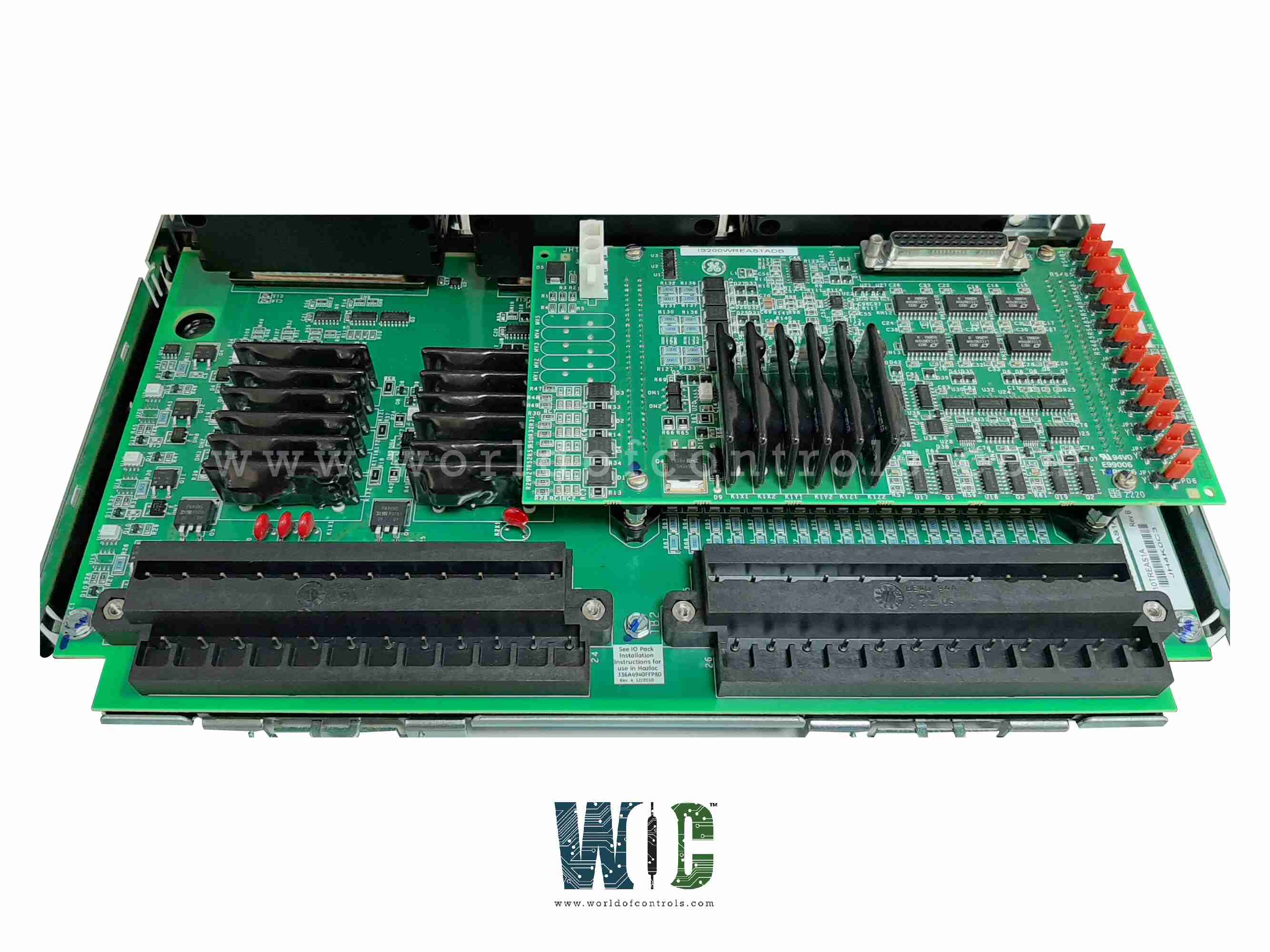
IS230TREAH4A - Turbine Emergency Trip terminal board

IS230TREAH4A - Turbine Emergency Trip terminal board IS230TREAH4A - Turbine Emergency Trip terminal board

World Of Controls understands the criticality of your requirement and works towards reducing the lead time as much as possible.

IS230TREAH4A - Turbine Emergency Trip terminal board is available in stock which ships the same day.

IS230TREAH4A - Turbine Emergency Trip terminal board comes in UNUSED as well as REBUILT condition.

To avail our best deals for IS230TREAH4A - Turbine Emergency Trip terminal board, contact us and we will get back to you within 24 hours.

SPECIFICATIONS

Part Number: IS230TREAH4A
Manufacturer: General Electric
Series: Mark VIe
Size: 33.0 cm high x 17.8 cm, wide
Technology: Surface mount
Temperature: -30 to 65oC
MPU pulse rate range: 2 Hz to 20 kHz
MPU pulse rate accuracy: 0.05 percent
Availability: In Stock
Product type: Turbine Emergency Trip terminal board
Country of Manufacture: United States (USA)

Functional Description

IS230TREAH4A is a Turbine Emergency Trip terminal board developed by GE. It is a part of the Mark VIe control system. The Aero Derivative Turbine Emergency Trip (TREA) terminal board, when combined with the WREA option card, functions as a critical component within the Mark VIe system, interfacing with PPRA turbine I/O packs. This setup plays a vital role in the monitoring and control of aero derivative turbines, especially in emergency situations. The TREA terminal board's inputs and outputs are designed to ensure efficient and reliable performance.

Features

  • Customer Input Terminals: The terminal board offers flexible customer input terminals through various configurations to meet different system requirements. It provides two 24-point pluggable barrier terminal blocks (H1A or S1A) or 48 pluggable Euro-style box terminals (H3A or S3A). These terminals allow for secure and reliable connections, facilitating seamless integration with customer-specific input needs. The pluggable design ensures ease of installation and maintenance, while the barrier and Euro-style options cater to varying connection densities and preferences.
  • Pulse Rate Devices: A key feature of the terminal board is its support for up to six fanned passive pulse rate devices. These devices are crucial for measuring turbine speed by sensing the rotations of a toothed wheel. The system can monitor up to three shafts, with two sensors per shaft, providing accurate and reliable speed measurements. This capability is essential for effective turbine monitoring and control, particularly in emergency scenarios where precise speed data is critical for safe operation.
  • Integration with the Mark VIe System: The board is designed to integrate seamlessly with the WREA option card and PPRA turbine I/O packs as part of the Mark VIe control system. This integration enhances the system's ability to manage turbine operations, ensuring robust safety and performance features. The combination of these components allows for the efficient execution of emergency trip functions and other critical monitoring tasks, contributing to the overall reliability of the turbine control system.
  • Terminal Block Details: The terminal blocks provided are essential for connecting multiple inputs securely. The 24-point pluggable barrier terminal blocks offer a convenient and safe method for wiring, while the 48 pluggable Euro-style box terminals provide a higher connection density in a compact format. These design choices ensure that the terminal board can accommodate various system configurations and facilitate reliable electrical connections.
  • Pulse Rate Device Operation: The six fanned passive pulse rate devices play a vital role in monitoring turbine speed. By detecting the rotations of a toothed wheel on the turbine shafts, these devices generate pulse rates that the system uses to determine the turbine's speed accurately. This precise measurement is critical for both regular operation and emergency situations, ensuring that the turbine operates within safe parameters and enabling timely responses to any speed-related issues.

Installation

  • Align the Connectors: Begin by aligning the two connectors on the WREA with those on the TREA. Proper alignment is crucial to ensuring a secure and functional connection. When viewing the WREA, the bottom of the board is identified as the end with the row of configuration jumpers. This orientation helps in correctly positioning the board for alignment. The connectors are designed with keys that ensure they will only mate when properly aligned. This feature helps prevent incorrect connections and potential damage to the boards.
  • Seat the Connection: Once the connectors are correctly aligned, seat the connection by firmly pressing on the four screw heads that surround the connector. This action ensures that the connectors are fully engaged, providing a stable and secure electrical connection. Applying even pressure on all four screw heads helps achieve a uniform connection, reducing the risk of loose or intermittent connections.
  • Inspect for Damage: Before starting the installation, inspect both the WREA and TREA boards for any visible damage or debris that could interfere with the connection. Clean the connectors if necessary.
  • Ensure Proper Orientation: Pay close attention to the orientation of the boards. Misalignment can lead to improper connections and potential damage to the components.
  • Use Appropriate Tools: If needed, use appropriate tools to apply firm and even pressure on the screw heads. Avoid using excessive force, which could damage the connectors or the boards.
  • Verify Connection: After seating the connection, visually inspect the connectors to ensure they are fully mated and securely fastened. A properly seated connection is essential for reliable operation.

Speed Inputs

  • First Shaft: The PR1_X and PR4 speed inputs must be wired to the two-speed sensors on the first shaft. This ensures that the speed of the first shaft is accurately monitored.
  • Second Shaft (if present): The PR2_X and PR5 speed inputs must be wired to the two speed sensors on the second shaft. This configuration allows for precise monitoring of the second shaft's speed.
  • Third Shaft (if present): The PR3_X and PR6 speed inputs must be wired to the two speed sensors on the third shaft. This setup ensures that the speed of the third shaft is accurately recorded.
  • Jumpers P1 and P2: Jumpers P1 and P2 must be placed on the TREA to take the first three speed inputs (those for the X pack) and fan them to the Y and Z packs. This configuration allows the speed inputs to be shared across multiple packs. When the jumpers are in place, the terminal board points for the Y and Z speed inputs become no-connects. These points should not be used, as the speed inputs are already fanned out from the X pack.
  • Jumper Position Feedback Signal: A feedback signal is provided by TREA to confirm the correct placement of the jumpers. This signal acts as a check to ensure that the system is configured correctly.
  • PPRA Alarm: If the jumpers are not in place, a PPRA will be generated. This alarm serves as a warning that the speed input configuration is incorrect and needs to be addressed to ensure proper operation.

WOC is happy to assist you with any of your GE requirements. Please contact us by phone or email for pricing and availability on any parts and repairs.

FREQUENTLY ASKED QUESTIONS

What is IS230TREAH4A?
It is a Turbine Emergency Trip terminal board developed by GE.

What ensures that the connectors will only mate when aligned properly?
The connectors are keyed to ensure that they will only mate when properly aligned. This design feature prevents incorrect connections and potential damage to the boards.

What should I do after aligning the connectors?
Once the connectors are aligned, you should seat the connection by firmly pressing on the four screw heads that surround the connector. This action ensures a stable and secure electrical connection.

Why is it important to apply even pressure on all four screw heads?
Applying even pressure on all four screw heads helps achieve a uniform connection, reducing the risk of loose or intermittent connections. This ensures the reliability of the connection.