SPECIFICATIONS
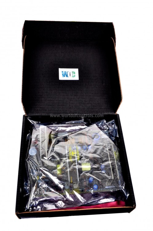
Part No.: IS230TPROH3C
Manufacturer: General Electric
Country of Manufacture: United States of America (USA)
Temperature Operating: -30 to 65 o C
Size: 33.0 cm x 17.8 cm
Product Type: Turbine Protection Board
Availability: In Stock
Series: Mark VI
Functional Description
IS230TPROH3C is a Turbine Protection Board developed by GE. It is a part of Mark VI control system. TPRO's Role in Emergency Overspeed and Synchronization Protection
TPRO serves a critical role by providing speed signals, temperature signals, generator voltage, and bus voltage to the VPRO. This forms an independent emergency overspeed and synchronization protection system. The protection system consists of triple redundant VPRO boards, which operate independently in a separate module from the turbine control system. It's important to note that TPRO is not compatible with the Mark VIe I/O packs, operating separately within this system architecture.
Protection System Components
- VPRO Functionality: The VPRO boards are responsible for executing the emergency trip function. These boards are connected to TPRO and control the trip solenoids through TREx (TREG, TREL, or TRES) terminal boards.
- Trip Solenoid Connections: Up to three trip solenoids can be connected between TREx and TRPx (TRPG, TRPL, or TRPS) terminal boards. TREx provides the positive side of the 125 V dc to the solenoids, while TRPx supplies the negative side. Both boards to trip the turbine.
Control and Relay Operations
- VPRO Control: VPRO operates the emergency overspeed protection and emergency stop functions. It manages 12 relays on the TREG board, with nine forming three groups of three to vote inputs controlling the three trip solenoids.
- TREG Board Operations: A secondary TREG board can be driven from VPRO through J4, extending control capabilities.
Operation
- It serves as a pivotal component within the turbine protection system, primarily responsible for supplying essential signals to the VPRO to ensure emergency overspeed (EOS) protection for the turbine's safe operation. Its key functions encompass providing speed signals critical for overspeed protection and generator signals for backup synchronization check protection.
- It manages three analog current inputs and nine thermocouple inputs, primarily utilized for exhaust over-temperature protection in gas turbines, ensuring comprehensive safety measures in various operational scenarios.
- In addition to its signal supply role, the TPRO relies on the VPRO to power the three analog input transmitters by providing 28 V dc. Speed control and overspeed protection are crucial functionalities executed by the TPRO through a complex monitoring setup.
- Employing six passive magnetic speed pickups, the TPRO divides its monitoring scheme into two segments. The first set of three pickups is monitored by the controller, which utilizes the median signal for speed control and acts as the primary overspeed protection measure. Conversely, the second set of three pickups is independently connected to the three VPROs within the protection module, enhancing redundancy and supplementing overspeed protection capabilities.
- The TPRO terminal board is designed for scalability, accommodating up to nine passive magnetic speed pickups or active pulse rate transducers (TTL type). This provision allows for further expansion of monitoring capabilities, enabling comprehensive overspeed protection facilitated by the VPROs. Overall, the collaborative efforts between the TPRO and VPRO within the turbine protection system create a robust framework, ensuring emergency overspeed protection, synchronization backup, and meticulous management of critical signals, thereby reinforcing safety measures essential for gas turbine operations.
Configuration
- Identify Jumper Locations: Before configuring the terminal board, refer to the installation diagram to locate the jumpers (JPA1 and JPB1). These jumpers play a crucial role in determining the input type and connection options.
- Jumper JPA1 Selection: Jumper JPA1 allows for the selection of either current input or voltage input based on system requirements. This jumper determines the type of signal the terminal board will accept from connected sensors or devices. By configuring JPA1, you can ensure compatibility with the input signals provided to the terminal board.
- Jumper JPB1 Configuration: Jumper JPB1 provides flexibility in configuring the return connection. Depending on the application and system design, this jumper can be set to connect the return to a common reference or left open. The configuration of JPB1 influences how the terminal board handles the return signal, which is essential for proper signal processing and system operation.
- Toolbox Configuration for VPRO: While jumpers JPA1 and JPB1 handle basic configuration aspects, the more advanced settings are configured using the Toolbox software. The Toolbox provides a user-friendly interface for adjusting various parameters, tuning settings, and optimizing performance based on specific system requirements. This includes configuring VPRO-related parameters to ensure seamless integration and functionality within the overall system architecture.
The WOC team is always available to help you with your Mark VI requirements. For more information, please contact WOC.
Frequently Asked Questions
What is IS230TPROH3C?
It is a turbine protection board developed by GE under Mark VI series.
What role does TPRO play in the protection module?
TPRO provides inputs crucial for backup synchronization check within the protection module, ensuring reliability in synchronization processes.
How are generator and bus voltages supplied within the system?
Generator and bus voltages are sourced from two single-phase potential transformers (PTs) with secondary output rated at a nominal 115 V rms.
What is the maximum cable length permissible between PTs and the turbine control?
The maximum allowable cable length between the PTs and the turbine control is 100 meters, utilizing 18 AWG twisted, shielded wire for optimal signal transmission.
