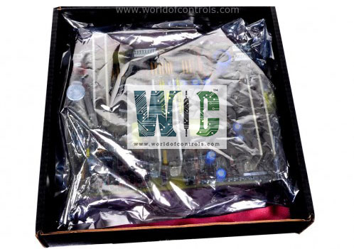
SPECIFICATIONS
Part No.: IS230TNVBH3A
Manufacturer: General Electric
Country of Manufacture: United States of America (USA)
Temperature Operating: 0 to 60 o C
Product Type: Vibration Input Assembly
Availability: In Stock
Series: Mark VIe
Functional Description
IS230TNVBH3A is a Vibration Input Assembly developed by GE. It is a part of Mark VIe control system. It is designed to work with various transducers for Keyphasor and vibration inputs, accommodating a wide range of sensor types and configurations.
Vibration Inputs
- Supports several types of transducers for vibration measurement, including Proximitor, seismic, Velomiter, and accelerometers (with the first three inputs on PVIB or YVIB modules being compatible with accelerometers). The vibration signal is superimposed upon a DC bias voltage, which is essential to fit within the defined input voltage range specified in the corresponding tables.
- For a proper vibration signal configuration, a -11 V DC bias should be added to the B/N buffered signal. When the model is configured for seismic transducers, an additional negative bias is necessary for open circuit detection. Furthermore, opening the PRxxL signal allows for a true differential reading and meets common mode rejection requirements. For open circuit readings of the gap voltage (DC component), the values should be more positive than -1.0 V DC for Proximitor, accelerometer, and Velomiter, while for seismic sensors, the value should be more negative than -15 V DC.
Position Inputs
- The position inputs of the model require that the open circuit reading for the gap voltage (DC component) be more positive than -1.0 V DC.
- This ensures accurate positioning measurements and reliable performance in various applications.
Phasor Inputs
- Similar to the position inputs, the phasor inputs of the model must have an open circuit reading for the gap voltage (DC component) that is more positive than -1.0 V DC. This consistency in requirements helps maintain the reliability and precision of the system.
Probe Power Supplies
- Voltage Supply: Each channel provides a -24 V power supply. This voltage level is standard for many probes and transducers, ensuring compatibility with a wide range of equipment.
- Current Output: The power supply can deliver a maximum current of 12 mA. This current capacity is sufficient for powering most probes, providing them with the necessary energy to operate accurately and reliably.
- Current Limiting: The supply is current limited to meet Class 1, Division 2 requirements. This safety feature prevents excessive current flow, which can protect both the probes and the power supply from damage due to overcurrent conditions. The current limiting feature ensures that the system adheres to stringent safety standards, making it suitable for use in hazardous locations where safety is paramount.
- Output Voltage Range: The output voltage range is specified as -24.5 V, with a tolerance from -23 V to -26 V. This range ensures that the power supply can accommodate minor variations in the power delivery, maintaining consistent performance of the probes under different operating conditions.
- Safety and Compliance: The design of the power supply channels adheres to Class 1, Division 2 requirements. This classification is critical for equipment used in environments with potentially explosive atmospheres, ensuring that the model can be safely deployed in such settings.
The WOC team is always available to help you with your Mark VIe requirements. For more information, please contact WOC.
Frequently Asked Questions
What is IS230TNVBH3A?
It is a Vibration Input Assembly developed by GE under the Mark VIe series.
What types of transducers are compatible with vibration inputs?
The Assembly supports Proximitor, seismic, Velomiter, and accelerometers (with accelerometer compatibility limited to the first three inputs on PVIB or YVIB modules).
What is the purpose of adding a DC bias voltage to the vibration signal?
The DC bias voltage ensures that the vibration signal fits within the defined input voltage range, enabling accurate measurements.
What bias voltage should be added to the B/N buffered vibration signal?
A -11 V DC bias should be added to the B/N buffered vibration signal.
