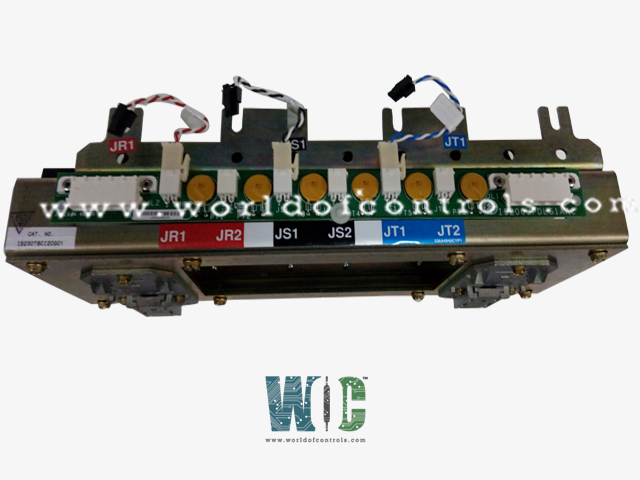
World Of Controls understands the criticality of your requirement and works towards reducing the lead time as much as possible.
IS230TBCIH2C - Contact Input with Group Isolation Terminal Board is available in stock which ships the same day.
IS230TBCIH2C - Contact Input with Group Isolation Terminal Board comes in UNUSED as well as REBUILT condition.
To avail our best deals for IS230TBCIH2C - Contact Input with Group Isolation Terminal Board, contact us and we will get back to you within 24 hours.
SPECIFICATIONS:
Part Number: IS230TBCIH2C
Manufacturer: General Electric
Series: Mark VIe
Product Type: Contact Input with Group Isolation Terminal Board
Number of channels: 24
Excitation voltage: 125 Vdc
Power supply voltage: 28 V dc
Voltage Range: 14 to 32 V dc
Mounting: DIN-rail mounting
Technology: Surface mount
Operating temperature: -30 to 65�C
Size: 33.02 cm high x 10.16 cm
Repair: 3-7 Day
Availability: In Stock
Manual: GEH-6421M
Country of Origin: United States
FUNCTIONAL DESCRIPTION:
IS230TBCIH2C is a Contact Input with Group Isolation Terminal Board manufactured and designed by General Electric as part of the Mark VIe Series used in GE Distributed Gas Turbine Control Systems. The Contact Input with Group Isolation (TBCI) terminal board accepts 24 dry contact inputs wired to two barrier-type terminal blocks. DC power is wired to TBCI for contact excitation. The contact inputs have noise suppression circuitry to protect against surge and high-frequency noise. In the Mark VIe system, the TBCI works with the PDIA I/O pack and supports simplex, dual, and TMR applications. One, two, or three PDIAs can be plugged directly into the TBCI. Mark VIe requires the C version of this board for correct mechanical alignment of connector JT1 with I/O pack mechanical support.
INSTALLATION:
Connect the wires for the 24 dry contact inputs directly to two I/O terminal blocks on the terminal board. These blocks are held down with two screws and can be unplugged from the board for maintenance. Each block has 24 terminals accepting up to #12 AWG wires. A shield terminal strip attached to the chassis ground is located immediately to the left of each terminal block. In a simplex system, connect TBCI to the I/O processor using connector JR1. In a TMR system, connect TBCI to the I/O processors using connectors JR1, JS1, and JT1. Cables or I/O packs are plugged in depending on the type of Mark VI or Mark VIe system, and the level of redundancy.
OPERATION:
Filters reduce high-frequency noise and suppress surge on each input near the point of signal entry. The dry contact inputs on TBCI_IC are powered from a floating 125 V de (100-145 V dc) supply from the turbine control. The 125 V de bus is currently limited in the power distribution module before feeding each contact input. The H2, H3, and H4 versions use lower voltages
The discrete input voltage signals pass to the PDIA I/O pack, which sends them through optical isolators providing group isolation and transfers the signals to the Mark VIe controller. The reference voltage in the isolation circuits sets a transition threshold that is equal to 50% of the applied floating power supply voltage. The tracking is clamped to go no less than 13% of the nominal rated supply voltage to force all contacts to indicate open when the voltage dips below this level.
A pair of terminal points are provided for each input, with one point (screw) providing the positive de-source and the second point providing the return (input) to the board. The current loading is 2.5 mA per point for the first 21 inputs on each terminal board. The last three have a 10 mA load to support the interface with remote solid-state output electronics. Contact input circuitry is designed for NEMA Class G creepage and clearance.