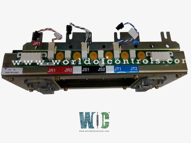
SPECIFICATIONS
Part Number: IS230TBCI2CG
Manufacturer: General Electric
Series: Mark VIe
Input filter: Hardware filter, 4 ms
Power consumption: 20.6 W on the terminal board
Size: 33.02 cm high x 10.16 cm wide
Temperature: -30 degrees Celsius to 65 Celsius.
Product type: Contact Input with Group Isolation Terminal Board
Country of Manufacture: United States (USA)
Functional Description
IS230TBCI2CG is a contact Input with Group Isolation Terminal Board developed by General Electric. It is a part of the Mark VIe series. The terminal board Contact Input with Group Isolation (TBCI) accepts 24 dry contact inputs wired to two barrier-type terminal blocks. For contact excitation, TBCI is wired with DC power. Surge and high-frequency noise are protected by noise suppression circuitry in the contact inputs.
Compatibility
- Designed for seamless integration with the PDIA (Process Data Input/Output) pack. It can effectively support simplex (single-channel), dual (two-channel), and TMR (Triple Modular Redundancy) configurations, enhancing its adaptability in different operational environments. Users can connect one, two, or even three PDIAs directly to the TBCI (Turbine Control Bus Interface), allowing for flexible system design and expansion.
- For optimal mechanical alignment of connector JT1 with the I/O pack's mechanical support, it is crucial to utilize the C version of this board within the Mark VIe system. This ensures precise connectivity and alignment, which are essential for maintaining system integrity and performance.
Operation
- The operational design of the system incorporates several key features that enhance signal integrity and reliability. Each input is equipped with filters positioned near the signal entry points, which serve to reduce high-frequency noise and suppress voltage surges. This proactive approach minimizes the risk of signal distortion, ensuring accurate data transmission.
- The dry contact inputs on terminal H1 are powered by the turbine control’s floating 125 V DC supply, which operates within a range of 100 to 145 V DC. Before feeding each contact input, the 125 V DC bus undergoes current limitations within the power distribution module. This step is crucial for protecting the system from potential overcurrent conditions that could cause damage or malfunction.
- Once the discrete input voltage signals are received, they are routed to the I/O processor. The I/O processor then sends these signals through optical isolators, which provide necessary group isolation. This isolation is vital for protecting sensitive components from electrical noise and transients, further enhancing the overall reliability of the system.
- The isolation circuits utilize a reference voltage that establishes a transition threshold, set to 50% of the applied floating power supply voltage. This careful calibration ensures that the system accurately interprets input signals and maintains operational stability.
Wiring
The wiring setup for the system involves connecting the 24 dry contact inputs directly to two I/O terminal blocks situated on the terminal board.
- Terminal Block Installation: These terminal blocks are securely fastened with two screws and can be easily disconnected from the board for maintenance purposes.
- Terminal Block Specifications: Each block is equipped with 24 terminals capable of accommodating wires up to #12 AWG in size.
- Shield Terminal Strip: Adjacent to each terminal block, there is a shield terminal strip connected to the chassis ground, facilitating effective grounding for the system and minimizing the risk of electromagnetic interference.
- Reliable Connection: This wiring configuration ensures a reliable and robust connection for the dry contact inputs, essential for the proper functioning of the system.
Cabling Connections
- Simplex System Setup: For a simplex system setup, connector JR1 serves as the primary interface point.
- Triple Modular Redundancy (TMR) Configuration: In a TMR configuration, all three connectors - JR1, JR5, and JT5 - come into play, ensuring redundancy and fault tolerance.
- Mark VI and Mark VIe Compatibility: The choice between Mark VI and Mark VIe systems influences the cabling approach.
- Mark VIe System Integration: In a Mark VIe system, I/O packs are plugged into the Terminal Board Control Interface (TBCI) and affixed to side-mounting brackets.
- Ethernet Connectivity: One or two Ethernet cables are then connected to the pack, facilitating communication and potentially requiring firmware downloads for optimal system performance.
- Adaptability for Redundancy: The cabling setup allows for seamless adaptation to varying redundancy requirements, ensuring robust and reliable operation in diverse industrial environments.
WOC is happy to assist you with any of your GE automation requirements. Please contact us by phone or email for pricing and availability on any parts and repairs.
FREQUENTLY ASKED QUESTIONS
What is IS230TBCI2CG?
It is a Contact Input with Group Isolation Terminal Board developed by General Electric
Is TBCI compatible with the PDIA I/O pack?
Yes, TBCI is compatible with the PDIA I/O pack and can handle simplex, dual, and TMR applications.
How many PDIAs can be directly connected to the Terminal Board?
One, two, or three PDIAs can be directly connected to the TBCI.
How does Board provide group isolation?
The discrete input voltage signals are routed to the I/O processor, which sends them through optical isolators to provide group isolation before sending them to the system controller. The isolation circuits' reference voltage establishes a transition threshold equal to 50% of the applied floating power supply voltage.
