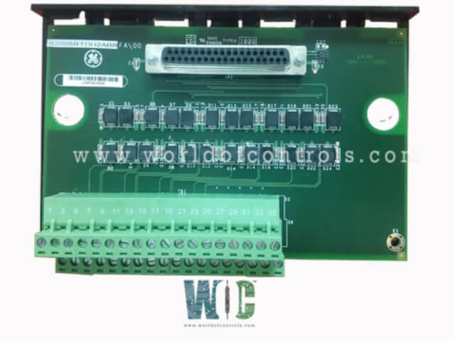
IS220SRTDH2A - Simplex RTD Board

IS220SRTDH2A - Simplex RTD Board IS220SRTDH2A - Simplex RTD Board

World Of Controls understands the criticality of your requirement and works towards reducing the lead time as much as possible.

IS220SRTDH2A - Simplex RTD Board is available in stock which ships the same day.

IS220SRTDH2A - Simplex RTD Board comes in UNUSED as well as REBUILT condition.

To avail our best deals for IS220SRTDH2A - Simplex RTD Board, contact us and we will get back to you within 24 hours.

SPECIFICATIONS

Part No.: IS220SRTDH2A
Manufacturer: General Electric
Country of Manufacture: United States of America (USA)
Size: 17.8 cm wide x 33.02 cm high
Temperature: -30 to + 65oC
Technology Surface-mount
Product Type: Simplex RTD Board
Availability: In Stock
Series: Mark VIe

Functional Description

IS220SRTDH2A is a Simplex RTD Board developed by GE. It is a part of the Mark VIe control system. It is engineered with a compact design, offering flexibility for DIN-rail or flat mounting configurations. This versatility allows for seamless integration into various system setups, accommodating different installation requirements. Within Mark VIe systems, the SRTD collaborates seamlessly with the PRTD I/O pack. This integration involves the I/O pack interfacing through a DC-37 pin connector and establishing communication with the controller via Ethernet connectivity. It's important to note that this compatibility is exclusively available for simplex systems.

Features

  • Multiple RTD Inputs: With a total of eight RTD inputs, the SRTD board provides ample capacity for connecting multiple sensors. These inputs enable the board to receive temperature data from various points within the system, contributing to comprehensive temperature monitoring.
  • Connectivity to I/O Processors: The board interfaces with either the PRTD or VRTD I/O processor, facilitating communication and data exchange between the RTD inputs and the processor. This connection ensures efficient processing of temperature data and enables the board to effectively contribute to system control and monitoring functions.
  • Euro-Block Terminal Blocks: Mounted on the board are high-density Euro-block type terminal blocks, which provide secure and reliable connections for wiring. These terminal blocks offer robustness and ease of use, facilitating straightforward installation and maintenance procedures.
  • Integrated ID Chip for Diagnostic Identification: An onboard ID chip plays a crucial role in identifying the board to the I/O processor for diagnostic purposes. This chip enhances system diagnostics by providing essential information about the board, aiding in troubleshooting and maintenance tasks.

Installation

  • Mounting Configuration: Along with a plastic insulator, it is mounted onto a sheet metal carrier, which in turn is affixed to a DIN rail. Alternatively, the SRTD and insulator can be mounted on a sheet metal assembly directly bolted into a cabinet.
  • Terminal Block Connection: Equipped with a Euro-style box type terminal block, featuring 36 terminals in two types. The eight RTDs are directly wired to this terminal block. Typically, 18 AWG wires, such as shielded twisted triplets, are used for wiring purposes.
  • Shield Terminal: It's important to note that there is no shield terminal strip included in this design. If shielded wiring is utilized, an external mounting bracket supplied by GE or the customer must be used for the I/O cable shield terminal.
  • Unused Terminals: Terminals 25 through 34 on the terminal block are not connected during installation.
    Grounding: Mounting holes labeled E1 and E2 serve as attachment points for the chassis ground screw connection (SCOM), ensuring proper grounding of the SRTD assembly.

Diagnostics

In normal operating conditions, the RUN status is indicated by a flashing green LED, while a solid red LED signifies a FAIL condition. The third LED remains off under normal circumstances but illuminates a steady orange to indicate the presence of a diagnostic alarm condition on the board. The diagnostic checks encompass two primary types: hardware limit checking and system limit checking, ensuring thorough scrutiny of all inputs:

  • Hardware Limit Checking: Each RTD type undergoes hardware limit checking based on preset high and low levels situated near the operational range extremes. If these limits are exceeded, a logic signal is triggered, and the input ceases to be scanned. Any hardware limit set for the 00 input triggers a composite diagnostic alarm, denoted as L3DIAG PRTD, pertaining to the entire board. Detailed diagnostics for individual signals are accessible through the toolbox. Additionally, these diagnostic signals can be individually latched and reset using the RESET DIA signal.
  • System Limit Checking: System limit checking is performed on each RTD input based on configurable high and low levels. These limits can be configured to generate alarms and can be toggled between enable/disable and latching/non-latching modes. The RESET SYS signal resets any out-of-limit signals. In TMR systems, limit logic signals are voted, and the resulting composite diagnostic is available in each controller.

The WOC team is always available to help you with your Mark VIe requirements. For more information, please contact WOC.

Frequently Asked Questions

What is IS220SRTDH2A?
It is a Simplex RTD Board developed by GE under the Mark VIe series.

What are the indicators of normal operation and failure on the PRTD?
In normal conditions, the RUN status is indicated by a flashing green LED, while a solid red LED signifies a FAIL condition. Additionally, a steady orange LED indicates the presence of a diagnostic alarm condition.

What types of diagnostic checks are performed on the PRTD inputs?
The PRTD undergoes hardware limit checking and system limit checking on its inputs to ensure comprehensive scrutiny.

What is hardware limit checking, and how does it work?
Hardware limit checking involves preset high and low levels near the operational range extremes. If these limits are exceeded, a logic signal is triggered, and the input ceases to be scanned.

What is the significance of the diagnostic alarm denoted as L3DIAG PRTD?
L3DIAG PRTD indicates a composite diagnostic alarm triggered by any hardware limit set for the 00 input, referring to the entire board. Detailed diagnostics for individual signals are available through the toolbox.