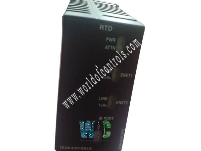
World Of Controls understands the criticality of your requirement and works towards reducing the lead time as much as possible.
IS220PRTDH1A - Resistance Temperature Device Input Module is available in stock which ships the same day.
IS220PRTDH1A - Resistance Temperature Device Input Module comes in UNUSED as well as REBUILT condition.
To avail our best deals for IS220PRTDH1A - Resistance Temperature Device Input Module, contact us and we will get back to you within 24 hours.
Part Number: IS220PRTDH1A
Manufacturer: General Electric
Series: Mark VIe
Product Type: Input Module
Number of Channels: 8
A/D Converter Resolution: 14-bit
Common Mode Voltage Range: ±5 Volts
Maximum Lead Resistance: 15 Ω maximum
Availability: In Stock
Country/Region of Manufacture: United States(USA)
Manual: GEH-6721L
IS220PRTDH1A is a Resistance Temperature Device Input Module manufactured and designed by General Electric as part of the Mark VIe Series used in distributed control systems. An RTD input terminal board and one or more I/O Ethernet networks are connected electrically by the Resistance Temperature Device (RTD) Input (PRTD) pack. An acquisition board dedicated to the thermocouple input function is included in the pack, along with a processor board that is shared by all Mark VIe distributed I/O packs. Up to eight RTD inputs can be supported by the I/O pack, while the TRTD terminal boards can support up to sixteen RTD inputs. A DC-37 pin connector that links directly to the terminal board connector for the pack, as well as a three-pin power input, are used for input. There are two RJ45 Ethernet connectors for the output. Indicator LEDs are used to display visual diagnostics.
Fig 1: PRTD Block Diagram
The RTD input terminal boards TRTDH1D, H2D, and SRTD board are all compatible with PRTDH1A, but the DIN-rail mounted DRTD board is not. The compatibility information is provided in the table below.
The TRD input circuit is galvanically isolated by the PRTD. This necessitates modifications to the TRTDH1D and TRTDH2D boards' terminal board transient protection. The board's H1D version offers filtering that is compatible with the PRTD standard scan rate. When the rapid scan rate of PRTD is chosen, the H2D version of the terminal board offers less filtering to enable proper performance. Although there won't be any physical harm, if PRTD is mounted on an earlier version of the TRTD board, an incompatibility will be detected.
The I/O pack or module function-specific acquisition board is connected to the processor board. The soft-start circuit ramps up the voltage available on the processor board when input power is applied. The processor reset is turned off and the local power supply is turned on in order. After finishing self-test routines, the processor loads application code from flash memory that is particular to the I/O pack or module type. To verify that the application code, acquisition board, and terminal board are correctly matched, the application code reads the board ID information. When there is a good match, the processor makes an effort to start Ethernet connections by asking for a network address.
The dynamic host configuration protocol (DHCP), which is the industry standard, and the terminal board's unique identifier are both used in the address request. Following Ethernet startup, the CPU runs the application, programs the on-board logic, and permits the acquisition board to start working.
The whole circuitry required to enable the I/O pack to function from one or two Ethernet inputs is contained in the processor application code. Both network pathways are constantly active when two Ethernet inputs are used. The I/O pack or module operation will not be hampered by a failure of either network, and the functioning network connection will reveal the failure. Compared to a traditional hot-backup system, where the second port is only used when the primary port fails to function, this configuration is more fault tolerant. The processor's Ethernet ports automatically negotiate between half-duplex and full-duplex operation at speeds between 10 MB/s and 100 MB/s.
The processor board is common to all Mark VIe Ethernet I/O packs or modules. It contains the following:
WOC has the largest stock of GE Speedtronic Mark VIe Replacement Parts. Our team of experts at WOC is happy to assist you with any of your automation requirements. For pricing and availability on any parts and repairs, kindly get in touch with our team by phone or email.
What is GE Mark VIe IS220PRTDH1A?
IS220PRTDH1A is a Resistance Temperature Device Input Module developed by General Electric and used in distributed control systems.
How to Check Price and Availability For IS220PRTDH1A?
Please Contact World of Controls FZE for sales at +1 609 385 1231 or Request a Quote.
What is the Common mode voltage range?
Common mode voltage ranges from + or - 5 volts.
What is the Maximum lead resistance of the component?
The Maximum lead resistance is 15 Ohm (two-way cable resistance)
What is the Normal mode rejection Rejection of the component?
Normal mode rejection Rejection of up to 250 mV rms is 60 dB at 50/60 Hz system frequency for normal scan.
How are boards packaged for shipment from WOC?
Parts are placed in antistatic packets and securely packed in ESD boxes cushioned with ESD Foam designed to safeguard electrical components.