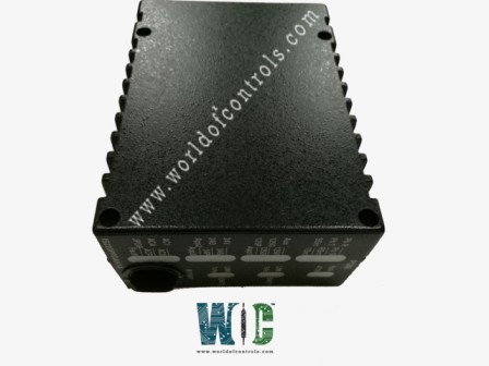
IS220PPDAH1A - Power Distribution System Feedback

IS220PPDAH1A - Power Distribution System Feedback IS220PPDAH1A - Power Distribution System Feedback

World Of Controls understands the criticality of your requirement and works towards reducing the lead time as much as possible.

IS220PPDAH1A - Power Distribution System Feedback is available in stock which ships the same day.

IS220PPDAH1A - Power Distribution System Feedback comes in UNUSED as well as REBUILT condition.

To avail our best deals for IS220PPDAH1A - Power Distribution System Feedback, contact us and we will get back to you within 24 hours.

SPECIFICATIONS

Part Number: IS220PPDAH1A
Manufacturer: General Electric
Series: Mark VIe
Product Type: I/O Pack
Availability: In Stock
Country/Region of Manufacture: United States
Manual: GEH-6721_Vol_II V

FUNCTIONAL DESCRIPTION

IS220PPDAH1A is a Power Distribution System Feedback Board manufactured and designed by General Electric as part of the Mark VIe Series used in distributed control systems. The Power Distribution System Feedback (PPDA) I/O pack can receive inputs from as many as six power distribution boards or as many as six sets of feedback signals. It offers the controllers a second redundant Ethernet interface while adjusting the board feedback signals. In order to identify the power distribution boards hooked into the PPDA feedback, electronic IDs are used in a plug-and-play design. By populating the IONet output with this data, connected boards can subsequently receive accurate feedback.

The Mark VIe Control Power Distribution Module's JPDS, JPDM, JPDG, or JPDC 28 V de control power distribution board serves as the host for the PPDA I/O pack (PDM). 50-pin ribbon cable jumpers wired pin to pin 1 are used to connect other boards. The PPDA receives one feedback group from each board.

The PPDA I/O pack includes one of the following compatible BPPx processor boards:

  • There is a BPPB processor board inside the PPDAHIA.
  • The ControlST software package V04.07 and later is compatible with the functionally compatible BPPC processor board found within the PPPDAHIB.
  • The JPDB, JPDE, and JPDF feedback signals are compatible with the PPDA I/O pack.


INSTALLATION:

  • Mount the selected terminal board firmly.
  • Directly connect the JAI terminal board connectors to the PPDA I/O pack. The JPDG, JPDS, JPDM, or JPDC 28 V de control power distribution board is where the PPDA I/O pack is mounted.
  • Using the threaded screws next to the Ethernet ports, mechanically secure the I/O pack. The studs slip into a mounting bracket made for the particular style of the terminal board. It is important to position the bracket such that the DC-62 pin connector connecting the I/O pack and the terminal board is not subjected to right-angle forces. In the course of the product's service life, the adjustment should only be necessary once.
  • Depending on how the system is set up, connect one or two Ethernet wires. Either port can be used to use the I/O pack. If twin connections are employed, it is customary to link ENETI to the network related to the R controller.
  • Connect the pack's connector to a power source to turn on the battery. The I/O pack includes a built-in soft-start feature that limits current inrush when power is applied, so it is not essential to unplug the cable before connecting it.
  • If necessary, set up the I/O pack using the ToolboxST program. Consult the section
  • Ribbon cables should be connected from connection P2 on JPDG, JPDS, JPDM, or JPDC to additional core boards supplying data to PPDA.


SIGNAL ROUTING:

The JPDG, JPDS, JPDM, or JPDC board is where the PPDA I/O pack is mounted. 50-pin ribbon cable jumpers wired pin to pin 1 are used to connect other boards. One feedback group is contributed to PPDA by each board. There are up to five prior boards that this connection goes through. This connection can be seen in the following figure.
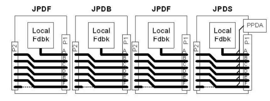
PPDA Basic Hookup Diagram


Fig 1: PPDA Basic Hookup Diagram

Feedback groups are shown in the above diagram as bold lines, and each board's connectors P1 and P2 are also shown. The PPDA I/O pack and connectors on the JPDS board are as follows, going from right to left:

  • JDPS has provided local comments on signal group A.
  • Signal group B is the subject of JPDF's feedback.
  • Signal group C is the subject of JPDB's feedback.
  • A further JPDF would employ signal group D.
  • Another board might make use of signal group E

JPDM uses two sets of feedback signals because that board has a substantial number of feedback lines. Utilizing two boards is supported by JDPM. The following illustration would represent the setup.
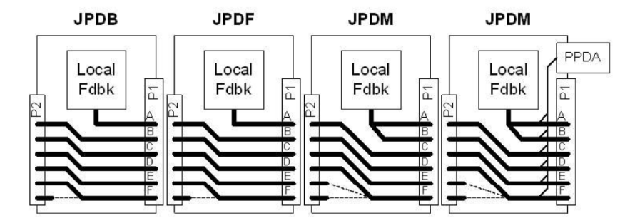
PPDA Wiring using Two JPDM Boards

 Fig 2: PPDA Wiring using Two JPDM Boards

DIAGNOSTICS:

  • A power-up self-test that examines the majority of the processor board components, Ethernet ports, RAM, and flash memory monitoring the internal power supply continuously to ensure proper operation.
  • Verification that the hardware set matches using the electronic ID data from the terminal board, acquisition card, and processor card, followed by verification that the application code loaded from flash memory is appropriate for the hardware set.
  • Precision reference voltages are included in each scan of the analog input circuitry.
  • The health of the A/D converter circuits is verified by comparing measured values to expected values. The ToolboxST program provides information about specific diagnoses.


CONFIGURATION:

For operation with desired PDM boards, the PPDA I/O pack utilizes configuration values. For the specific PDM hardware version being used in a system, the ToolboxST program offers the appropriate options. The following is a list of the different configurations that have been encountered:

JPDB:

  • For each of the two ac buses, the nominal voltage magnitude, the magnitude tolerance, and the neutral voltage correction factor are all specified.
  • It is possible to turn on or off the status of each fused switched branch circuit.

JPDC:

  • If P28R, S, and T are possible in a system, the PPDA has to know about it. The low voltage diagnostics for that power bus can be disabled if it appears that none is present, as stated.
  • You can customize the 125 V bus magnitude and centering tolerance as well as toggle on or off the diagnostic for switched branch circuit fuse conditions.
  • When using an ac input, the nominal voltage magnitude, magnitude tolerance, and an ac bus neutral voltage adjustment factor are all supplied. You can turn on or off the status of each fuse in a switched branch circuit.

JPDG:

  • The P28 feedback and diagnostics are switchable It is advised to leave them on.
  • The switched branch circuit fuse status diagnostic can be turned on or off, as well as the 24/48 V bus magnitude and centering tolerance.
  • JPDE:
  • The switched branch circuit fuse status diagnostic and the 24 V bus magnitude and centering tolerance configurations are also switchable.

JPDF:

  • You can specify the 125 V bus magnitude, centering tolerance, and switch on or off the diagnostic for switched branch circuit fuse condition.

JPDS/JPDM:

  • A system's ability to contain P28R, S and T must be known to the PPDA. The low voltage diagnostics for that power bus can be disabled if it is reported that one is not present.

PPDA:

  • The diagnostic daisy chain's PDM boards must be known to the LO pack.

WOC has the largest stock of GE Speedtronic Mark VIe Distributed Control System Replacement Parts. We can also repair your faulty boards. WORLD OF CONTROLS can also supply unused and rebuilt backed-up with a warranty. Our team of experts is available round the clock to support your OEM needs. Our team of experts at WOC is happy to assist you with any of your automation requirements. For pricing and availability on any parts and repairs, kindly get in touch with our team by phone or email.

FREQUENTLY ASKED QUESTIONS

What is GE Mark VIe IS220PPDAH1A?

IS220PPDAH1A is a Power Distribution System Feedback developed by GE and used in Distributed Control Systems.

How to Check Price and Availability For Power Distribution System Feedback?

Please Contact World of Controls FZE for sales at +1 609 385 1231 or Request a Quote.

How are Boards Packaged For Shipment from WOC?

Parts are placed in antistatic packets and securely packed in ESD boxes cushioned with ESD Foam designed to safeguard electrical components.