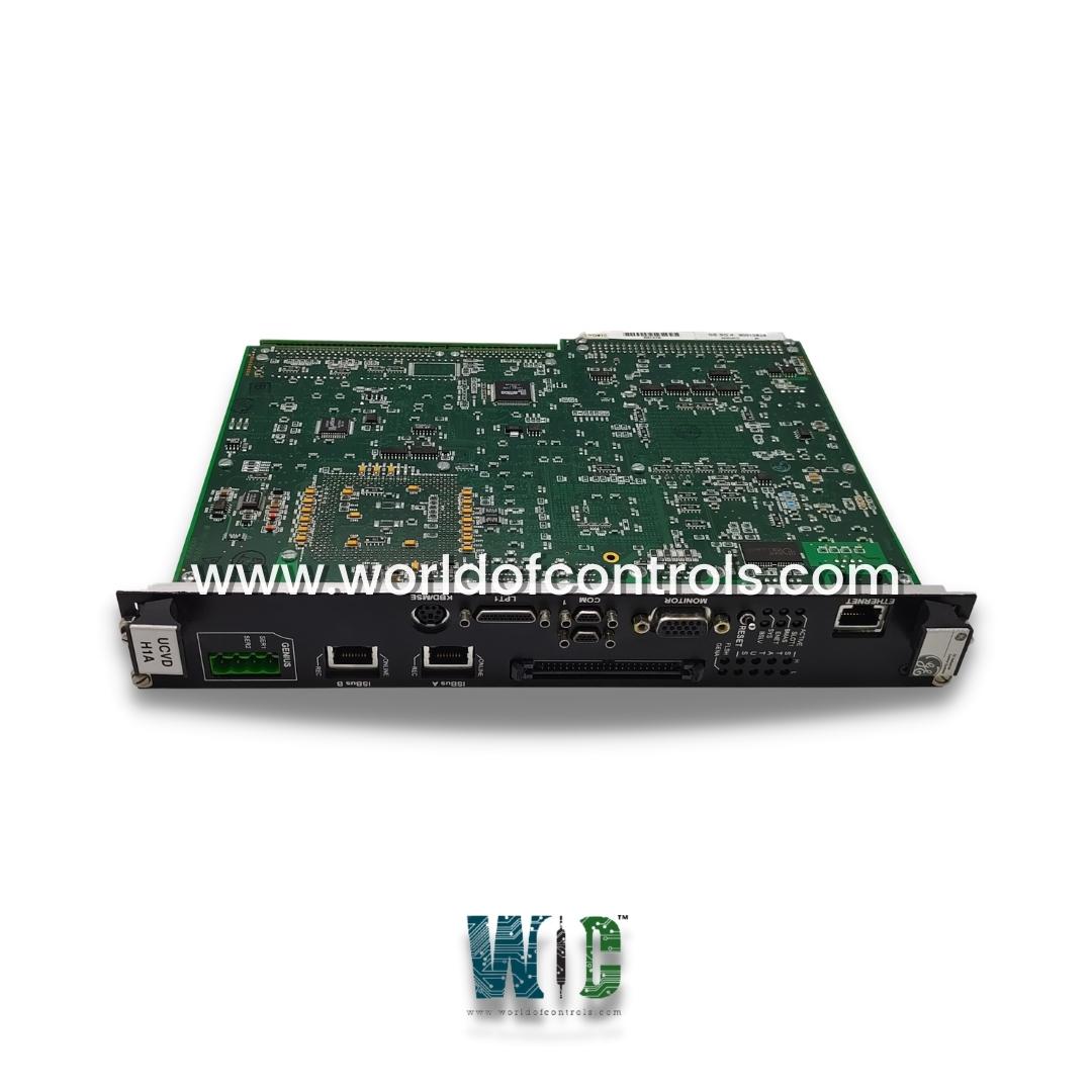
IS215UCVDH2AA - Double-slot Board

IS215UCVDH2AA - Double-slot Board IS215UCVDH2AA - Double-slot Board

World Of Controls understands the criticality of your requirement and works towards reducing the lead time as much as possible.

IS215UCVDH2AA - Double-slot Board is available in stock which ships the same day.

IS215UCVDH2AA - Double-slot Board comes in UNUSED as well as REBUILT condition.

To avail our best deals for IS215UCVDH2AA - Double-slot Board, contact us and we will get back to you within 24 hours.

SPECIFICATIONS

Part No.: IS215UCVDH2AA
Manufacturer: General Electric
Country of Manufacture: United States of America (USA)
Microprocessor: AMD-K6 300 MHz
Operating System: QNX
Product Type: Double-slot Board
Availability: In Stock
Series: Mark VI

Functional Description

IS215UCVDH2AA is a double-slot board developed by GE. It is a part of the Mark VI control system. It is designed to facilitate user interaction, provide visual status indications, and process essential data. It features a double-slot board housing a robust 300 MHz AMD K6 processor. This powerful processor is complemented by 8 MB of flash memory and 16 MB of DRAM, ensuring efficient data processing and storage capabilities. The combination of these elements provides the necessary computational resources for handling complex control and display functions.

Features

  • Equipped with a single 10BaseT (RJ-45 connector) Ethernet port, establishing connectivity to the UDH (User Data Handler). This Ethernet connection enables seamless communication, allowing the UCVD to receive and transmit crucial data to and from the central control system.
  • A distinctive feature is the presence of a double column comprising eight status LEDs. These LEDs serve as an intuitive visual indicator of the system's operational status. In normal operation, the LEDs are sequentially turned on in a rotating pattern, providing a clear visual confirmation of the controller's healthy functioning.
  • During normal operation, the component employs a rotating pattern for the status LEDs. This dynamic visual display serves not only as an aesthetic element but also as a functional indication that the controller is operating optimally. The rotating sequence is a visual cue to operators, confirming the ongoing health of the system.
  • In the event of an error condition or malfunction, the status LEDs on the module take on a new role. Instead of the rotating pattern, the LEDs display a flashing error code that specifically identifies the nature of the problem. This immediate visual feedback is invaluable for quick diagnostics and troubleshooting.
  • The flashing error code emitted by the LEDs serves as a diagnostic tool, allowing maintenance personnel to swiftly identify and address issues. This feature streamlines the troubleshooting process, reducing downtime and ensuring rapid response to potential faults.
  • With its visually intuitive LED display and error code system, provides a user-friendly interface. This interface enhances the overall user experience, empowering operators and maintenance personnel with a clear and accessible means of monitoring the system's health.
  • It adopts a double-slot configuration to accommodate the processing demands and incorporate the necessary components for effective user control and display functionalities. This design choice ensures optimal performance and seamless integration within the broader control system architecture.

LEDs

  • ACTIVE LED: Illuminates when the processor is active. This LED serves as a real-time confirmation that the UCVD is operational, actively processing data, and contributing to the overall functionality of the control system.
  • SLOT 1 LED: Provides information about the configuration of the controller within the VME rack. When illuminated, it indicates that the UCVD is configured as the slot 1 controller in the VME rack. This visual cue aids in quickly identifying the specific role of the UCVD within the broader system architecture.
  • BMAS LED: Signals VME master access, indicating that the UCVD is currently engaging in VME master activities. This status is crucial for understanding the ongoing communication and data exchange processes within the VME (Versa Module Europa) bus.
  • ENET LED: Insight into Ethernet activity. When illuminated, it signifies that the UCVD is actively engaged in data transmission or reception over the Ethernet connection. This visual cue is particularly useful for monitoring network-related activities.
  • BSLV LED: Indicates VME slave access, signifying that the UCVD is participating in VME slave activities. This LED is essential for monitoring the UCVD's interactions within the VME bus, allowing for a quick assessment of its role in data exchange.
  • STATUS LED: Plays a dual role, serving as an indicator of normal operation and as a diagnostic tool during fault conditions. During normal operation, the STATUS LED displays a rotating LED pattern, visually confirming that the UCVD is functioning correctly. In the event of a fault, it switches to a flashing mode, providing a clear and immediate error code for diagnostic purposes.
  • FLSH LED: Signifies that the UCVD is currently writing to Flash memory. This visual indicator helps in monitoring crucial system activities related to the storage and retrieval of data from the Flash memory, which is often used for non-volatile storage of critical information.
  • GENX LED: Informs users that the Genius I/O is active. Genius I/O refers to an intelligent I/O system, and the illumination of this LED indicates that the UCVD is currently utilizing or processing data from the Genius I/O modules. This status is especially relevant for systems employing Genius I/O technology.

Expansion on Ethernet Interface in the System

  • The Ethernet interface in the control system employs a standard twisted pair 10BaseT connection with an RJ-45 connector. This widely adopted configuration ensures compatibility and ease of integration with various networking components and devices.
  • The communication between the controller and the toolbox is facilitated using the TCP/IP protocol. This protocol, part of the Internet Protocol suite, ensures reliable and seamless data exchange between the controller and the toolbox, supporting a variety of applications and services.
  • For communication between the controller and the Human Machine Interface (HMI), the Serial Request Transfer Protocol (SRTP) is utilized. SRTP is a protocol specifically designed for supervisory control and data acquisition (SCADA) systems, offering efficient and real-time data exchange between the controller and the HMI.
  • The Ethernet Global Data (EGD) protocol is implemented to facilitate communication with the CIMPLICITY HMI and Series 90-70 Programmable Logic Controllers (PLCs). EGD is an open, standardized protocol that enables the seamless transfer of data between devices, promoting interoperability within the control system.
  • To communicate with third-party Distributed Control Systems (DCS), the control system supports the Ethernet Modbus protocol. Modbus is a widely used communication protocol in industrial automation, and its Ethernet variant enables efficient and standardized data exchange between the controller and external systems, enhancing interoperability.

Runtime Errors

  • Status LED Group Layout: The Status LED group on the controller boards consists of eight segments arranged in a two-vertical column layout. Each column represents a hexadecimal digit, with the right-most column representing the lower digit and the left-most column representing the upper digit. The least significant bits are located at the bottom.
  • Display of Controller Errors: The LEDs within the Status LED group display controller errors when a problem occurs during runtime. Each LED segment corresponds to a specific error code or fault condition, allowing operators to quickly identify and diagnose issues with the controller.
  • Hexadecimal Fault Code Representation: The hexadecimal digits displayed by the LEDs represent fault codes or error conditions encountered by the controller. These fault codes are converted into numerical representations for easier interpretation and troubleshooting. The numerical conversions provide a clear understanding of the error condition, aiding operators in identifying the root cause of the issue and taking appropriate corrective actions.
  • Fault Code Definitions: The fault code definitions associated with each numerical representation provide detailed information about the nature of the error or fault condition. By referencing these definitions, operators can gain insights into the specific issue affecting the controller and determine the appropriate course of action to resolve it.

The WOC team is always available to help you with your Mark VI requirements. For more information, please contact WOC.

Frequently Asked Questions

What is IS215UCVDH2AA?
It is a double-slot board developed by GE under the Mark VI series.

What is the UCVD and what are its key specifications?
It is a double-slot board equipped with a 300 MHz AMD K6 processor, 8 MB of flash memory, and 16 MB of DRAM. It features a single 10BaseT Ethernet port (RJ-45 connector) for connectivity to the UDH.

How does the UCVD connect to the control system network?
Utilizes a single 10BaseT Ethernet port with an RJ-45 connector for network connectivity. This connection facilitates communication with the UDH, ensuring seamless integration into the control system network.

What is the purpose of the double column of eight status LEDs?
The eight status LEDs serve as visual indicators of the board's operational status. In normal operation, these LEDs are sequentially turned on in a rotating pattern, providing a visual confirmation of the controller's healthy operation.