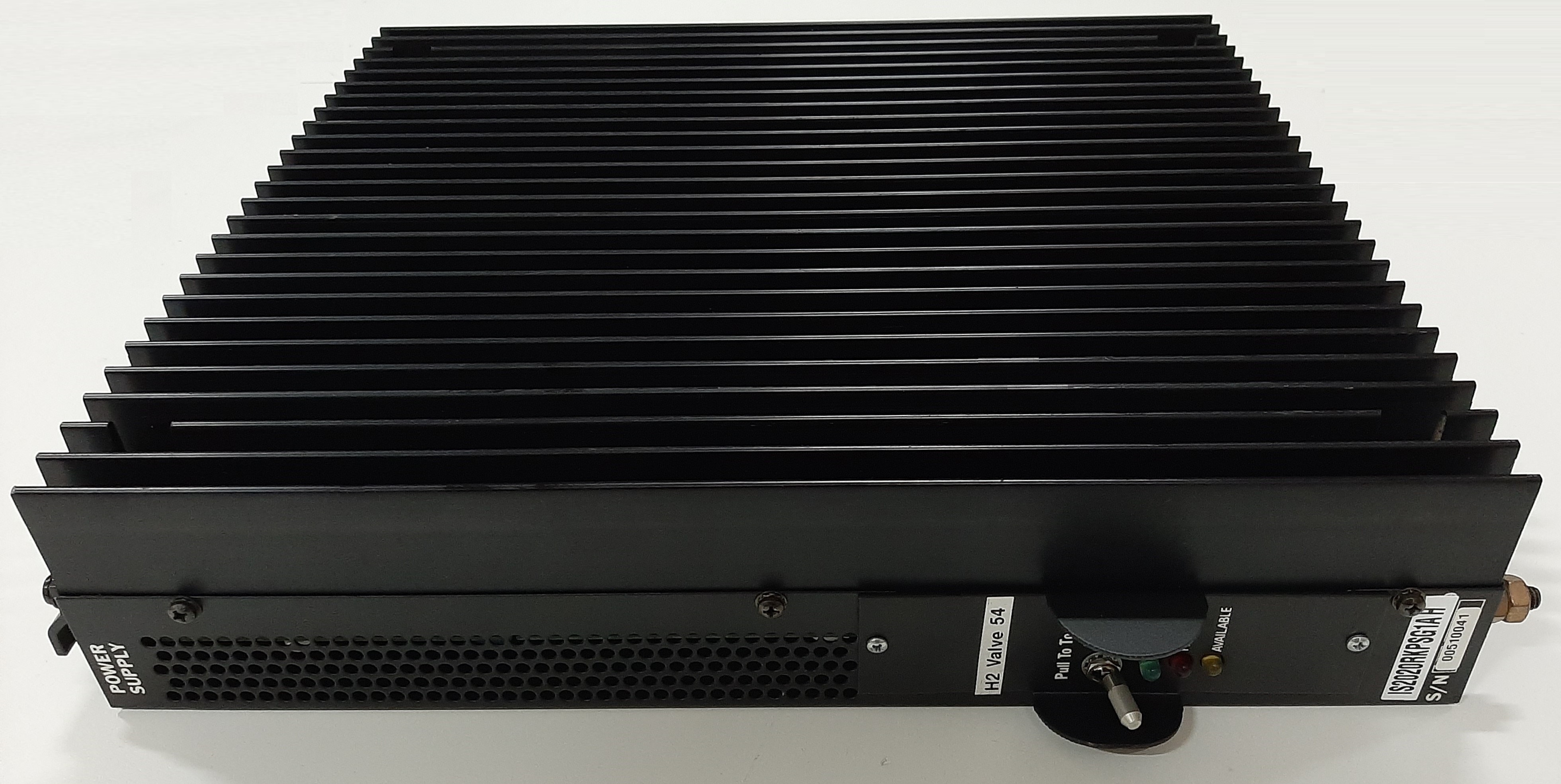
World Of Controls understands the criticality of your requirement and works towards reducing the lead time as much as possible.
IS2020RKPSG1A - VME Rack Power Supply Module is available in stock which ships the same day.
IS2020RKPSG1A - VME Rack Power Supply Module comes in UNUSED as well as REBUILT condition.
To avail our best deals for IS2020RKPSG1A - VME Rack Power Supply Module, contact us and we will get back to you within 24 hours.
SPECIFICATIONS:
Part Number: IS2020RKPSG1A
Manufacturer: General Electric
Series: Mark VI
Product Type: VME Rack Power Supply Module
Number of channels: 6
Input span: 4-20 mA
Termination resistors: 121 Ohm
Technology: Surface Mount
Common Mode Voltage Range: ±5 V
Maximum Lead Resistance: 15Ω
Analog output current: 0-20 mA
Operating temperature: -30 to 65 °C
Size: 15.9 cm high x 10.2 cm
Repair: 3-7 Day
Availability: In Stock
Country of Origin: United States
Manual: GEH-6421I
FUNCTIONAL DESCRIPTION:
IS2020RKPSG1A is a VME Rack Power Supply Module manufactured and designed by General Electric as part of the Mark VI Series used in GE Speedtronic Turbine Control Systems. The Mark VI VME rack power supply mounts on the side of the VME control and interface racks. It supplies +5, +12, +15, and +28 V dc to the VME backplane and an optional 335 V dc output for powering flame detectors connected to TRPG. Two supply input voltage selections are available. There is a 125 V dc input supply that is powered from a Power Distribution Module (PDM) and a low voltage version for 24 V dc operation.
INSTALLATION:
The power supply is mounted to the right-hand side of the VME rack on a sheet metal bracket. The dc input, 28 V dc output, and 335 V dc output connections are at the bottom. The newer design also has a status connector on the bottom. Two connectors, PSA and PSB, at the top of the assembly mate with a cable harness carrying power to the VME rack. Each of the five 28 V dc power modules supplies a section of the VME rack. These sections are labeled A, B, C, D, E, and F. The P28C output or PS28 at the bottom of the power supply can be used to power an external peripheral device. To do this the jumper plug shown on the bracket to the left of the rack must be moved from the Normal position to the Isolated position below.
OPERATION:
The VME Rack power supply has only one user control, the power switch, and three status LED indicators. The power switch provides front-panel control of the power supply output voltages and when toggled serves as a fault reset. The yellow, red, and green LEDs indicate the status of the input power, fault presence, and normal operation. The front panel power switch is a locking type that must be pulled out to change position. This switch is a low voltage control to enable or disable the output voltages. If the red LED is ON indicating a fault condition the power switch can be toggled OFF and then back ON again to clear the fault. The fault will only be cleared if the condition that caused it no longer exists.
WOC has the largest stock of GE Speedtronic Turbine control system OEM replacement parts. We can also repair your faulty boards and supply unused and rebuilt boards backed up with a warranty. Our team of experts is available round the clock to support your OEM needs. Our team of experts at WOC is happy to assist you with any of your automation requirements. For pricing and availability on any parts and repairs, kindly get in touch with our team by phone or email.
What are the main functions of the VME Rack Power Supply?
The primary function is to convert electrical power from an AC or DC source to the appropriate DC voltages required by the VME system. It also provides overvoltage, overcurrent, and thermal protection for the rack.
How do I select the right VME Rack Power Supply Module?
When selecting a power supply, consider the voltage and current requirements of your VME system, the type of input power available (AC or DC), the power rating, and any additional features such as redundancy or hot-swapping.
How do I maintain a VME Rack Power Supply Module?
Regular maintenance includes ensuring clean ventilation, checking for dust buildup, and verifying that all connections are secure. Also, inspect for any signs of wear, such as frayed wires or capacitor leaks.