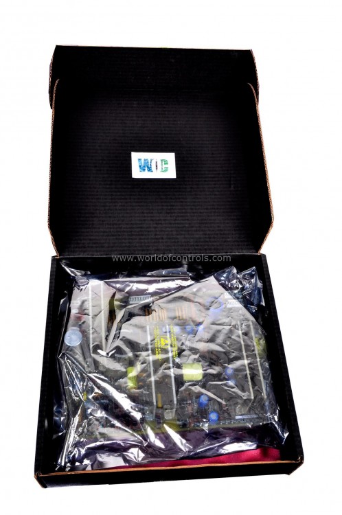
SPECIFICATIONS
Part No.: IC3606STMH
Manufacturer: General Electric
Product Type: Thermocouple Averaging Switch Board
Availability: In Stock
Series: VersaMax
Functional Description
IC3606STMH is a thermocouple averaging switch board developed by GE. It is a part of GE Mark I and II series. A thermocouple averaging switch board is a device used in industrial settings to manage multiple thermocouple inputs. These switchboards can average the temperature readings from several thermocouples, providing a more stable and accurate temperature measurement by reducing the impact of individual sensor fluctuations.
System Switch Settings
- VMPA/VMPC Switch Adjustment: The first step in configuring switch settings involves setting the VMPA/VMPC switch to the position that corresponds to the type of Printed Wiring Board (PWB) inserted into the extender board. This is a crucial step as it ensures that the test module is correctly configured to work with the specific PWB being tested. The switch essentially tells the test module which type of PWB it should expect to interact with.
- Power Application to the Turbine Control Panel: Following the correct adjustment of the VMPA/VMPC switch, the next step involves applying power to the turbine control panel. It's important to note that this step should only be taken after the switch settings are correctly configured. Applying power without the correct switch settings could lead to inaccurate testing or damage to the equipment.
- Test Module Readiness: Once the power is applied to the turbine control panel, the test module is now ready for use. The configuration of the switch settings ensures that the test module is set up to communicate effectively with the control panel and collect data accurately.
Troubleshooting
- LED Failure: If an LED fails to illuminate as expected, it is essential to address this issue promptly. Replace the faulty LED with a new one or exchange it with a known good LED that is mounted on the Printed Wiring Board (PWB). This step ensures that the LED itself is functioning correctly. If replacing the LED does not resolve the problem, it may be necessary to proceed to the next troubleshooting step.
- PWB Replacement: If LED replacement does not correct the issue, the next course of action is to remove and replace the HTAA Printed Wiring Board. This component may be causing the problem, and replacing it can restore the functionality of the test module.
- Electronic Circuit and Cable Checks: The electronic circuits and cables should be thoroughly checked with the test module connected to the turbine control panel. This check can be conducted while the turbine is shut down to ensure safety. During this process: Utilize standard DIRECTO-MATIC R II turbine operating procedures to manipulate the turbine control panel signals. Observe that the associated test panel LEDs accurately track the signal changes. This step is crucial for verifying the alignment of the electronic circuits with the control panel signals.
- Interconnection Diagram for Continuity Checks: Checks and signal tracing is valuable if there are suspicions of issues within the interface cabling. It serves as a visual guide for identifying and addressing potential continuity issues.
- First Fault Detection Circuit Test: The test module's first fault detection circuit can be tested with the test module connected to a turbine control panel with the FIRST FLT DET mode selected.
- During a normal turbine shutdown: Observe that only one LED within the first fault detection circuit (indicated by asterisks on the front panel) should indicate a trip condition. The signal that triggers the turbine trip may vary from one panel to another, depending on the specific application.
- HTAA PWB Suspicions: If the first fault function does not operate as expected, but the monitor mode does, the HTAA PWB should be suspected as the potential source of the problem. However, before replacing the PWB, it is advisable to check the toggle switch and associated wiring to rule out any wiring or switch-related issues.
The WOC team is always available to help you with your Mark I and II requirements. For more information, please contact WOC.
Frequently Asked Questions
What is IC3606STMH?
It is a thermocouple averaging switchboard developed by GE.
How can I test the first fault detection circuit in the test module?
To test the first fault detection circuit, connect the test module to a turbine control panel with the FIRST FLT DET mode selected. During a normal turbine shutdown, observe that only one LED within the first fault detection circuit should indicate a trip condition. The specific signal that triggers the turbine trip may vary.
When should I suspect the HTAA PWB is the source of the problem in the test module's first fault function?
If the first fault function doesn't operate correctly while the monitor mode does, you should suspect the HTAA PWB as a potential source of the problem. Before replacing the PWB, check the toggle switch and associated wiring.
Can the averaged temperature be integrated into a control system?
Yes, the averaged temperature output from the switchboard can be integrated into a control system for automated process adjustments or monitoring.
Is the switchboard output digital or analog?
The output can be either digital or analog, depending on the specific design of the switchboard. Some models offer both options.
