World Of Controls understands the criticality of your requirement and works towards reducing the lead time as much as possible.
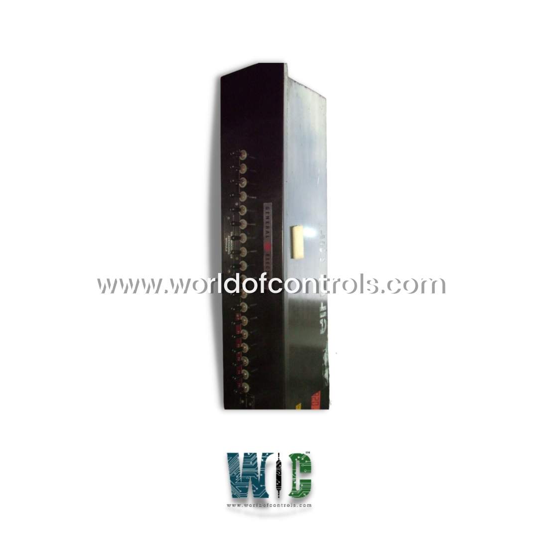
IC3603A271C - Thermocouple Averaging Module is available in stock which ships the same day.
IC3603A271C - Thermocouple Averaging Module comes in UNUSED as well as REBUILT condition.
To avail our best deals for IC3603A271C - Thermocouple Averaging Module, contact us and we will get back to you within 24 hours.
SPECIFICATIONS:
Part No: IC3603A271C
Manufacturer: General Electric
Product Type: Thermocouple Averaging Module
Series: Mark II
Number of Inputs: 4
Thermocouple Types Supported: J, K, T, E, N, R, S
Input Impedance: >10 MΩ
Analog Output: 4-20 mA
Output Load: 500 Ω max
Power Consumption: <5 W
Operating Temperature: -10°C to +60°C
Storage Temperature: -25°C to +85°C
Voltage: 18–36 VDC
Digital Output: RS-485 Modbus
Accuracy: ±0.25%
Board Size: 2.8 cm high x 8.6 cm
Weight: 0.45 kg
Availability: In Stock
Country of Origin: USA
FUNCTIONAL DESCRIPTION:
IC3603A271C is a Thermocouple Averaging Module manufactured and designed by General Electric as part of the Mark II Series used in GE Speedtronic Control Systems. The thermocouple provides an accurate and economical method for recording temperatures and for controlling the power required to heat a given surface area. Only one thermocouple has been used heretofore because no practical means existed for electrically insulating the thermocouples from the material being heated. For best control and computer operation, this single thermocouple has been located at the hottest known point in the area. Additional thermocouples, however, have been required to establish the hottest location, determine the temperature distribution, and monitor the tests. In the past, a normal test installation consisted of a control thermocouple and a spare in each control area. Loss of the control thermocouple, in most instances, would abort the test; a switching device would enable the spare to regain test control. Thermocouples connected in parallel to a common junction, on the other hand, would provide a mean area temperature and eliminate the problem of test abortion.
THERMOCOUPLE CONTROL SIGNAL FUNCTION:
The thermocouple acts as a remote device for providing the thermal inputs to the test structure through the error feedback signal to a heat rate computer or as a control signal to a power regulator. These equations represent requirements for unit areas, and thermal equilibrium must be achieved with Ts only when solving for the instantaneous power required. Ts, therefore, is the only true test parameter, and all other parameters are calculated and programmed into the computer to satisfy the remainder of the heat equation. The instantaneous skin or surface temperature, Ts, therefore, represents the mean temperature per unit area. Whenever an area of several square feet is being heated, the temperature of a single point will not describe the temperature for the entire heated surface. The parallel thermocouple circuit provided the simplest and most economical method of obtaining the mean surface temperature for remote equipment.
PRACTICAL APPLICATION OF GROUNDED PARALLEL THERMOCOUPLES:
The Law of Intermediate Metals and the Law of Intermediate Temperatures relate the theory of thermocouple emf's to temperature. We will not consider the Law of Intermediate Temperatures because the reference junction will not be involved; the effect between the measuring junctions cannot be accounted for as a separate part of the circulating emf. The thermal emf depends on the difference in temperature between the measuring and reference junctions and the wire materials used.
The Peltier and Seebeck effect governs the emf resulting solely from contact of two dissimilar metals, and its magnitude changes with temperature; intimate contact is not essential, and the individual leads may be any distance apart. The temperature of each wire, which represents the measuring junction circuit, determines the magnitude of the emf. Most applications use wires either welded together or separated by small distances (approximately 1/4 inch or less) and welded to the material being measured.
DC CIRCUIT FOR GROUNDED PARALLEL THERMOCOUPLES:
Each thermocouple measuring junction is considered a battery. To simplify the calculations, only three are connected in a parallel circuit. The actual thermocouple weld resistance and the metal plate resistance were measured. These resistances are so small that they can normally be neglected. The weld resistance is in series and is included in the total resistance of each thermocouple circuit. The problem is simplified by combining all resistances for each circuit.
WOC has the largest stock of OEM Replacement Parts for GE Speedtronic Gas Turbine Control Systems. We can also repair your faulty boards and supply unused and rebuilt boards backed up with a warranty. Our team of experts is available around the clock to support your OEM needs. Our team of experts at WOC is happy to assist you with any of your automation requirements. For pricing and availability on parts and repairs, kindly contact our team by phone or email.
What is the primary function of a Thermocouple Averaging Module?
A Thermocouple Averaging Module is designed to take input from multiple thermocouples and compute the average temperature across all connected sensors. This averaged value is then output as a single representative signal.
How does the module process multiple thermocouple inputs?
The module receives voltage signals from each connected thermocouple, converts them into temperature values using built-in thermocouple linearization algorithms, and then mathematically averages those temperature readings.
What is the typical output of a thermocouple averaging module?
Output options generally include analog signals such as 4-20 mA, 0-10 V, or voltage outputs proportional to temperature. Some advanced models may offer digital communication via protocols like Modbus RTU, Profibus, or Ethernet/IP, allowing for direct integration into modern control systems.