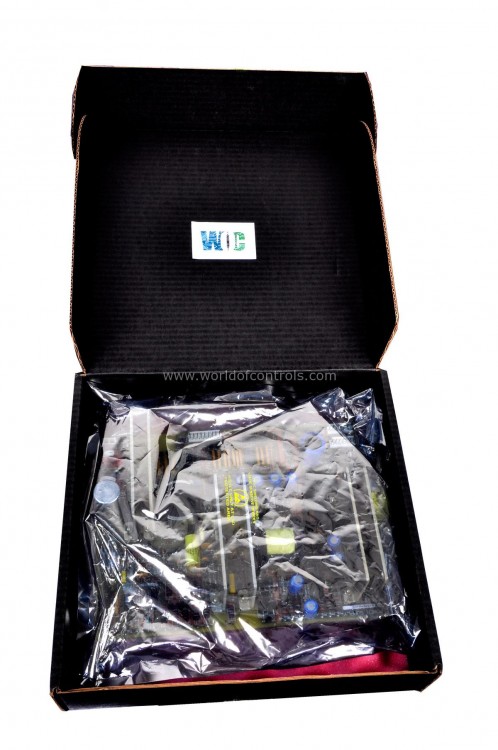
SPECIFICATIONS
Part No: IC3603A162B
Manufacturer: General Electric
Function: Heat Sink Transistor Assembly
Series: Mark I and II
Repair: 3-7 Day
Availability: In Stock
Country of Manufacturer: United States (USA)
Functional Description
IC3603A162B is a Heat Sink Transistor Assembly developed by GE. It is a part of Mark I and II control system. Although GE has developed newer control platforms like Mark V, VI, and VIe, many facilities still rely on the Mark I and II systems, particularly in legacy infrastructure. The heat sink transistor assembly remains vital in supporting these systems, allowing operators to maintain and refurbish older equipment without the need for a full system upgrade.
Key Features and Functions
- Thermal Management: The assembly combines heat sinks with transistors to dissipate excess heat generated by power transistors. This is critical in preventing overheating within the control system, especially in high-demand environments. By effectively dispersing heat, the assembly helps maintain optimal operating temperatures for the components, extending their life and preventing thermal-related failures.
- Power Regulation: The transistors within this assembly are responsible for power switching and regulation, essential for controlling various subsystems within the Mark I and II control systems. These transistors work in tandem with other components to modulate power supply to different modules, ensuring stable operation and preventing electrical surges or drops that could disrupt the turbine control system.
- Applications and Importance: The heat sink transistor assembly is essential in maintaining the efficiency and longevity of the Mark I and II control systems by handling power regulation and heat management. Its design supports stable and reliable operation, which is crucial in applications where turbine performance and safety are top priorities, such as in power generation and heavy industrial processes.
Temperature control system
- Constant Firing Temperature: The temperature control system is set to maintain a constant firing temperature across a range of ambient operating conditions. This approach ensures that the gas turbine performs optimally, regardless of external temperature fluctuations. Control lines, selected based on desired operating conditions, provide a slope that maintains consistent firing temperature, avoiding excessive thermal stress on the turbine.
- Exhaust Temperature Limitation: To protect the turbine's exhaust system, exhaust gas temperatures are limited to around 1000°F across all operational scenarios. This constraint prevents overheating and degradation of exhaust components, thereby enhancing overall system durability. For the LM2500 gas turbine model, this system includes a control that limits the inlet gas temperature to the load turbine, ensuring stable operation by maintaining this constant value.
- Integrated Temperature System (ITS): Single-shaft gas turbines employ an Integrated Temperature System (ITS), which coordinates with other control systems to regulate the firing and exhaust temperatures precisely. ITS details and functionality are typically described in further documentation, as it is a critical component in single-shaft turbine configurations.
- Heat Recovery Applications: Gas turbines used in applications with heat recovery systems are designed to operate with variable airflow over the load range to achieve maximum exhaust temperatures, optimizing the heat rate during part-load conditions. This variable airflow management is crucial in applications like combined heat and power (CHP) setups, where efficient thermal energy extraction from exhaust gases is desired.
- Methods of Airflow Variation: Compressor Inlet Guide Vane Angle: Adjusting the angle of the inlet guide vanes regulates the amount of air entering the compressor, thus controlling the airflow and maintaining ideal exhaust temperature at various load levels.
- Compressor Rotor Speed: For some gas turbines, airflow is adjusted by varying the compressor rotor speed. This is particularly beneficial in two-shaft gas turbines where speed adjustments allow for fine-tuned airflow control.
- Two-Shaft Gas Turbine Configuration: In two-shaft gas turbines with variable area second-stage nozzles, the airflow variation is unique. The turbine's axial flow compressor is driven by the high-pressure stage of a two-stage axial flow turbine. The second stage, or load turbine, connects directly to the driven equipment, with no mechanical link between the two turbine stages. Instead, the stages are aerodynamically coupled by variable-area second-stage nozzles. These nozzles adjust the energy distribution between stages, allowing independent control of compressor speed and airflow over the operating load range.
- LM2500 Model Specifics: The LM2500 gas turbine does not feature variable area nozzles. Instead, it provides variable airflow by a broad high-pressure speed range (from 500 to 9000 RPM). This wide range allows the LM2500 to handle load variations efficiently while keeping exhaust temperatures optimized.
WOC is happy to assist you with any of your GE requirements. Please contact us by phone or email for pricing and availability on any parts and repairs.
FREQUENTLY ASKED QUESTIONS
What is IC3603A162B?
It is a Heat Sink Transistor Assembly developed by GE.
How does the system control turbine output power?
The control system dynamically adjusts turbine output power over its load range to meet the current demand, ensuring efficient operation and responsiveness to load changes.
What is the purpose of the maximum output limitation?
The system includes a maximum output limitation to prevent the turbine from exceeding safe operational levels. This protects the unit from overloading and ensures operational reliability.
What are the advantages of the structured approach to turbine control?
This approach enhances efficiency, minimizes setup time in the field, and allows for flexible configuration to suit various industrial needs. By optimizing control and maintenance, it supports both reliability and operational performance.
