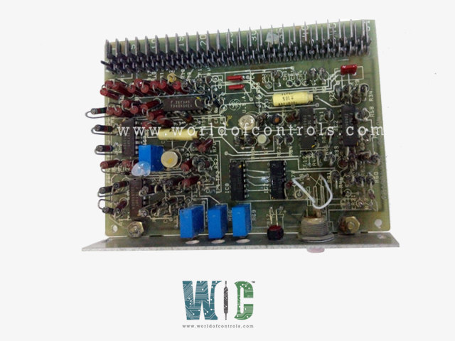
World Of Controls understands the criticality of your requirement and works towards reducing the lead time as much as possible.
IC3600STKK1 - Temperature Control Board is available in stock which ships the same day.
IC3600STKK1 - Temperature Control Board comes in UNUSED as well as REBUILT condition.
To avail our best deals for IC3600STKK1 - Temperature Control Board, contact us and we will get back to you within 24 hours.
Part No: IC3600STKK1
Manufacturer: General Electric
Function: Temperature Control Board
Series: Mark I and II
Repair: 3-7 Day
Availability: In Stock
Country of Manufacturer: United States (USA)
IC3600STKK1 is a Temperature Control Board developed by GE. It is a part of Mark I and II control system. It manages, and govern temperature signals, coupled with various input signals and an array of customizable adjustments, positions it as a pivotal element within the encompassing control system it is seamlessly integrated into.
The STKK card plays a pivotal role by receiving the exhaust temperature signal, known as TX, which originates from the thermocouple processing module. This temperature signal is critical for monitoring the temperature within the system.
Once received, the TX signal is combined or summed with various reference signals. This combined signal is then used to modulate the output voltage (VCE). This modulation of VCE, in turn, is responsible for controlling the flow of fuel within the system, making it an essential part of temperature regulation.
The STKK card is responsible for determining when TX should take control of the VCE bus. When TX is in control, the output TC is set to a logic 1, indicating that the system is actively regulating temperature. Conversely, when the system is not in control, TC! is set to a logic 0.
The card generates a base reference for the temperature control process. This base reference is adjustable using a component labeled R69. This adjustable base reference is fundamental to the precise control of temperature within the system.
The board also develops an ambient bias reference that plays a crucial role in temperature control. This reference is generated through an operational amplifier circuit equipped with offset and gain adjustments, ensuring that temperature control remains accurate.
The ambient bias circuit accommodates a variety of input signals, making it versatile. It can accept either a signal ranging from 0 to 1 millivolt on BVCE or a signal ranging from 0 to 5 volts on PCD. Furthermore, it can work with a 10-50 mA input signal by connecting it to PCD and jumpering PCD to CSA/B and CSA, or a 4-20 mA input with the same configuration.
The output of the ambient bias amplifier is available at the output pin PCDN, making it accessible for further use within the control system.
The STKK card provides the flexibility to connect additional reference signals to input SJ. Typically, this is where signals like start-up suppression, peak, and peak reserve signals are connected. These signals may be crucial for specific temperature control scenarios.
The board offers a range of adjustment options to fine-tune its performance, including:
WOC is happy to assist you with any of your GE requirements. Please contact us by phone or email for pricing and availability on any parts and repairs.
What is IC3600STKK1?
It is a Temperature Control Board developed by GE
How is temperature control achieved?
When TX takes control of the VCE bus, the output TC is set to a logic 1, indicating active temperature control. Conversely, TC! is set to a logic 0 when temperature control is not active.
How is the base reference for temperature control generated and adjusted?
The base reference is generated on the card and is adjustable using component R69. It can also be accessed at the output base.
What is the Ambient Bias reference?
The Ambient Bias reference is another reference signal developed on the card. It involves an operational amplifier with offset and gain adjustments.
What types of signals can be used as input to the Ambient Bias circuit, and how are they connected?
The Ambient Bias circuit can accept a 0 to 1m signal on BVCE or a 0 to 5V signal on PCD. Additionally, it can work with a 10-50 mA input signal by connecting to PCD and jumpering PCD to CSA/B and CSA, or a 4-20 mA input using the same configuration. The output of the Ambient Bias amplifier is available at output pin PCDN.