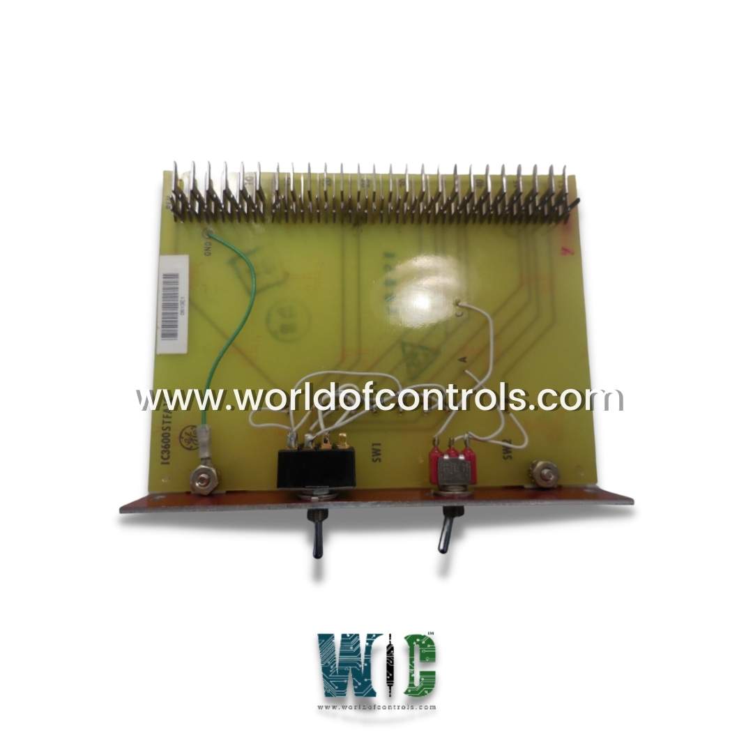
World Of Controls understands the criticality of your requirement and works towards reducing the lead time as much as possible.
IC3600STFA1 - Over Speed Test Board is available in stock which ships the same day.
IC3600STFA1 - Over Speed Test Board comes in UNUSED as well as REBUILT condition.
To avail our best deals for IC3600STFA1 - Over Speed Test Board, contact us and we will get back to you within 24 hours.
Part No: IC3600STFA1
Manufacturer: General Electric
Function: over speed test board
Series: Mark I and II
Repair: 3-7 Day
Availability: In Stock
Country of Manufacturer: United States (USA)
IC3600STFA1 is an overspeed test board developed by GE. It is a part of Mark I and II control system. The component within control systems, specifically designed for testing and ensuring the safety of the system by monitoring and controlling overspeed conditions. Its functions encompass gain adjustment, customizability through jumpers, digital setpoint inputs, and the ability to modulate acceleration to ensure safe and controlled operation. The board's features are critical for maintaining safety and efficiency in various industrial and machinery control applications.
WOC is happy to assist you with any of your GE requirements. Please contact us by phone or email for pricing and availability on any parts and repairs.
What is IC3600STFA1?
It is an over speed test board developed by GE
How does the overspeed trip system contribute to safety and reliability?
The overspeed trip system, with its two separate sensing circuits, enhances reliability and safety by providing redundancy in detecting and responding to overspeed conditions, minimizing the risk of equipment damage or failure.
What is the purpose of the overspeed test pushbutton on the board?
The overspeed test pushbutton serves as a manual control for testing the system's response to overspeed conditions. When activated, it feeds a negative bias into SJ, increasing NVCE, allowing operators to verify the system's effectiveness in responding to overspeed situations.
How can operators customize the card's response using jumpers between pin CC and CE?
Jumpers between pin CC and CE are used to set the desired transfer function, allowing operators to customize the card's response to specific input signals, making it adaptable to various control scenarios.
What is the role of Potentiometer RI 14 in the board, and how is it adjusted?
Potentiometer RI 14 provides a gain adjustment mechanism that allows operators to fine-tune the board's response to ensure precise control during overspeed conditions.