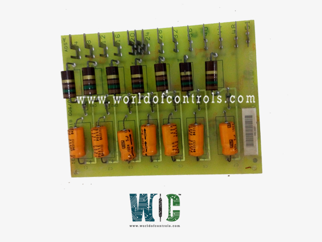
World Of Controls understands the criticality of your requirement and works towards reducing the lead time as much as possible.
IC3600SSDA1 - Set Control Contact Card is available in stock which ships the same day.
IC3600SSDA1 - Set Control Contact Card comes in UNUSED as well as REBUILT condition.
To avail our best deals for IC3600SSDA1 - Set Control Contact Card, contact us and we will get back to you within 24 hours.
SPECIFICATIONS:
Part Number: IC3600SSDA1
Manufacturer: General Electric
Series: GE Speedtronic Mark I / Mark II
Product Type: Set Control Contact Card
Number of Inputs: 8
Operating Modes: Current Mode or Voltage Mode
Input Data: 16-bit Input Data
Update Rate: 13 ms all channels
Backplane Current Consumption: 15 mA at 5V, 120 mA at 3.3V
Voltage Range: -10 to 10 Volts DC
Resolution at 0-20 mA: 5 microamps
Input Impedance: 250 ohms
Frequency: 50 to 60 Hertz
Internal Power Consumption: 120 mA
Availability: In Stock
Weight Approx: 0.25 – 0.40 kg
Country of Origin: United States
FUNCTIONAL DESCRIPTION:
IC3600SSDA1 is a Set Control Contact Card manufactured and designed by GE Mark II Series as part of the GE Speedtronic Gas Turbine Control Systems. The primary function of the Set Control Contact Card is to process logical inputs and activate control outputs, such as relays or contact closures, that initiate or maintain specific turbine operations. In simpler terms, the card performs a “set” action—once triggered by the control logic, it energizes a circuit or relay to turn something ON in the system, such as starting a motor or opening a valve. This activation is typically latched or held until another condition resets it. These cards are essential to maintaining precise control, sequencing, and safety within the turbine system.
INSTALLATION:
The card is designed as a modular, plug-in type printed circuit board (PCB) that mounts vertically into a designated slot within the control rack, interfacing with the system via a standardized edge connector. Before installation, the entire control system must be powered down to eliminate the risk of electrical damage or personal injury. The card should be handled using electrostatic discharge (ESD) precautions, such as an anti-static wrist strap, to protect its semiconductor components from static-related failure. Technicians should inspect the card for any signs of physical damage, corrosion, or contamination before proceeding.
OPERATIONS:
The card receives digital or discrete inputs from other logic elements in the system—these may include permissive signals, sensor validations, interlocks, or manual operator inputs. Once all logical prerequisites are met, the card transitions its output state from de-energized to energized, thereby completing a control circuit. This energized state is usually latched, meaning it will remain active until a reset condition or interlock is received from the associated Reset Control Card or equivalent logic chain.
WOC has the largest stock of OEM Replacement Parts for GE Speedtronic Control Systems. We can also repair your faulty boards and supply unused and rebuilt boards backed up with a warranty. Our team of experts is available around the clock to support your OEM needs. Our team of experts at WOC is happy to assist you with any of your automation requirements. For pricing and availability on parts and repairs, kindly contact our team by phone or email.
What type of output does the Set Control Contact Card provide?
The card provides a dry contact relay output that is latched upon receiving a valid input logic signal. This output can be used to energize external loads or initiate control sequences within the turbine system. The latching nature ensures the output remains active until a specific reset logic is applied.
What is the typical coil voltage and current rating for the output relay?
The output relays in these cards are typically rated for standard industrial DC or AC voltages, depending on the system design. For most GE Speedtronic Mark I/II implementations, the control voltage is 28 VDC, and the relay contacts are rated to handle low-power control circuits (e.g., 0.5 A at 28 VDC).
What are the input impedance and logic threshold voltage?
Exact values can vary depending on card revision, but typical input impedance ranges from 2kΩ to 10kΩ, and logic threshold voltages generally follow TTL standards. For example, a logical HIGH might be >2.4 VDC, while LOW is <0.8 VDC.