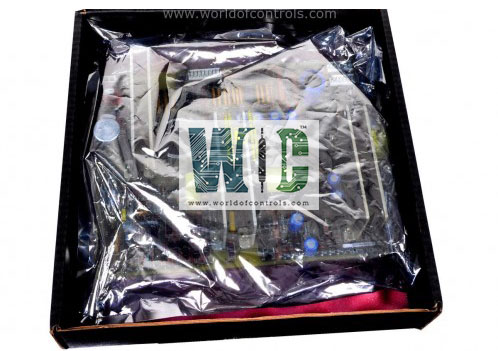
World Of Controls understands the criticality of your requirement and works towards reducing the lead time as much as possible.
IC3600SPRA1 - GE Fanuc Pulse Rate Circuit Board is available in stock which ships the same day.
IC3600SPRA1 - GE Fanuc Pulse Rate Circuit Board comes in UNUSED as well as REBUILT condition.
To avail our best deals for IC3600SPRA1 - GE Fanuc Pulse Rate Circuit Board, contact us and we will get back to you within 24 hours.
SPECIFICATIONS:
Part Number: IC3600SPRA1
Manufacturer: General Electric
Series: Mark I & II
Product Description: GE Fanuc Pulse Rate Circuit Board
Manufacturer: GE Fanuc
Backplane Current Consumption: 450 mA
Input Voltage Range: 24V DC
Input data: 244 Bytes
Baud rates: 9.6K, 19.2K, 93.75K
Current draw: 450mA
Operating Temperature: -20°C to +70°C
Mounting Type: DIN rail
Weight: 0.37 Kg
Shipping weight: 1.5 Kg
Country of Origin: United States
Availability: In Stock
FUNCTIONAL DESCRIPTION:
IC3600SPRA1 is a GE Fanuc Pulse Rate Circuit Board manufactured and designed by GE Mark I & II Series as part of the GE Speedtronic Gas Turbine Control Systems. The board counts the number of pulses received from sensors over a defined period, converting this data into actionable information. It includes components like amplifiers and filters that clean and stabilize the incoming pulse signals, removing noise or distortion that could affect the accuracy of the readings. The circuit board typically has a microcontroller or processor that interprets the pulse data, applies any necessary processing, and outputs the pulse rate or position information to a central control system. It communicates the processed pulse data to a central controller or automation system, allowing for real-time adjustments and control of machinery based on the pulse feedback.
FUNCTIONS OF PULSE RATE BOARD:
WOC has the largest stock of OEM Replacement Parts for GE Speedtronic Control Systems. We can also repair your faulty boards and supply unused and rebuilt boards backed up with a warranty. Our team of experts is available round the clock to support your OEM needs. Our team of experts at WOC is happy to assist you with any of your automation requirements. For pricing and availability on parts and repairs, kindly contact our team by phone or email.
What is the primary function of the GE Fanuc Pulse Rate Circuit Board?
The primary function of the GE Fanuc Pulse Rate Circuit Board is to receive pulse signals from external devices like encoders, tachometers, or proximity sensors, and convert these pulses into meaningful data that can be used to monitor and control parameters such as speed, position, or rotational count in industrial systems.
What types of signals can the Pulse Rate Circuit Board process?
The circuit board can process digital pulse signals generated by devices like rotary encoders, proximity sensors, and tachometers. These signals are typically used to monitor mechanical movements such as rotational speed or position.
How does the circuit board count pulses?
The board contains pulse counters, which increment with each pulse received. It calculates the pulse rate by counting the number of pulses in a specific time frame (frequency) and converts this information into speed or position data.