SPECIFICATIONS
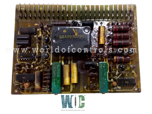
Part No: IC3600EPSA1
Manufacturer: General Electric
Function: Voltage Regulator Circuit Board
Series: Mark I & II
Repair: 3-7 Day
Availability: In Stock
Country of Manufacturer: United States (USA)
Functional Description
IC3600EPSA1 is a Voltage Regulator Circuit Board developed by GE. It is a part of Mark I & II control system.
Features
- Voltage Stabilization: Turbine control systems often involve various electrical and electronic components, such as sensors, actuators, and controllers. These components require a steady and consistent voltage supply to function accurately. The Voltage Regulator Circuit Board ensures that the voltage supplied to these components remains constant, regardless of fluctuations in the power source.
- Protection Against Voltage Spikes: Turbines can generate voltage spikes or surges during their operation, which could potentially harm sensitive electronic equipment. The Voltage Regulator Circuit Board acts as a safeguard by limiting and regulating the voltage to prevent damage to the connected devices.
- Voltage Reference: In some cases, precise voltage levels are necessary for specific control algorithms or feedback mechanisms in turbine control systems. The Voltage Regulator Circuit Board can provide a stable voltage reference for these purposes, ensuring accurate and reliable system performance.
- Improved System Efficiency: Maintaining a consistent voltage level enhances the overall efficiency of the turbine control system. It ensures that components operate within their optimal voltage range, reducing energy waste and minimizing the risk of overheating or electrical failures.
System Features
- The fuel control system is comprised of three primary loops, namely the startup, load turbine speed, and temperature loops. These loops are interconnected in a manner that establishes a minimum value gate, ensuring that the loop requiring the least amount of fuel takes precedence. In addition to the fuel control loops, two-shaft turbines feature a nozzle control loop responsible for positioning the nozzle angle to regulate high-pressure (HP) speed.
- The overall control system is meticulously designed to achieve the highest level of operational reliability. To enhance this reliability, redundant sensors are frequently employed to provide redundant feedback signals. This redundancy ensures that critical data is consistently available, even in the event of sensor failures. For instance, when the system is operating under speed control, the temperature control loop serves as a backup, reinforcing the system's reliability and safety measures. This approach helps maintain consistent and stable performance, safeguarding against unforeseen contingencies and contributing to the system's overall robustness.
WOC is happy to assist you with any of your GE requirements. Please contact us by phone or email for pricing and availability on any parts and repairs.
FREQUENTLY ASKED QUESTIONS
What is IC3600EPSA1?
It is a Voltage Regulator Circuit Board developed by GE
What are the primary loops in a fuel control system, and how do they operate together?
The fuel control system consists of three primary loops- the startup, load turbine speed, and temperature loops. These loops are interconnected with a minimum value gate, ensuring that the loop requiring the least amount of fuel is given priority.
What is the role of the nozzle control loop in two-shaft turbines within the fuel control system?
In two-shaft turbines, the nozzle control loop is responsible for positioning the nozzle angle to regulate high-pressure (HP) speed. This ensures precise control over turbine speed.
How is operational reliability maximized in the overall control system?
The overall control system is meticulously designed to achieve the highest level of operational reliability. This is accomplished through careful engineering and redundancy measures.
