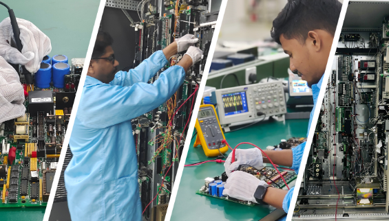
At WOC, we offer comprehensive GE Turbine Control System Troubleshooting Services for control cards and spares used in Control Panels, PLCs, DCSs, Drives, and Turbine Control panels. Our in-house facility is equipped with quality test equipment and staffed by experienced engineers and technicians with years of industry expertise. ...
This check is highly important as our hawk-eyed staff can usually identify the faults by observing the part closely. Our team looks out for any oddities on the board first. These can include to ensure that all the small components are in the right area, inspected to see if there are any component damages. It is vital to inspect any burn marks on the bAnalyzing oard, as this could indicate a high level of damage that prepare our engineers accordingly for the next steps. Team shall capture a image or make note of the discrepancies in the assembled circuit board that allows easy verification and ensures once the cleanup is completed.
The crew then moves to the next stage for analyzing the shorts between the power Bus and the ground Bus. If any shorts been detected, they move towards to identify and replace the shorted components, which will be covered in the following article. However, if no shorts are found, they move towards the Power - UP test and if found ok they move towards the functional test.
At this stage, The engineer used do the power up test with the help of a test rack/test benches to carefully analyze the board. Those are fully equipped racks and benches to inspect the parts in detail.
When inspection is completed, Team moves towards the live control test panel which is an important step, to identify further faults, hence the is inserted to the appropriate test panel such as GE Excitation and GE Speedtronic Mark V, Mark VI, Mark VIe or VIeS panels.
The technical team carefully monitors the operation of the card within the live control panel and keeps a watchful eye and observe all the functions and monitoring functional variations. This test will reveal if there are any faults within the card.
Once Fault been identified, they remove the card and move on to perform a component level test. The assessment will indicate the weak or non-functional components on the board and indicates that a non-functional or functionally weak diode, transistor, resistor, ICs or a capacitor could adversely affect the performance of the PCB. One other important factor could be perhaps aforementioned components been completely malfunctioned and needs replacement.
While the functional test is passed and the team is convinced, the card shall be discarded from the test panel and proceeded through an intensive ultrasonic cleaning process and left to dry. It is important that sufficient time passes the spares and needed to dry out completely. Subsequently, the circuit board is inserted into the live test control panel for a functional test of 48 hours. It is monitored to ensure, during those 48 hours, there is next to nil chances of failure and the part is in functional condition.
What precautions do engineers take when handling control boards?
Engineers wear electrostatic wrist straps to prevent static discharge, safeguarding the board.
Are there additional tasks during the functional test phase?
Yes, engineers download applicable firmware and configurations and reboot the control system. They also monitor controller-I/O card communication and check for diagnostic errors in Control ST.
What is checked during the functional test phase?
During the functional test, engineers download firmware and configurations, reboot the control system, and closely monitor communication between the controller and I/O cards. They also check for diagnostic errors in Control ST.
Why is it important to monitor controller-I/O card communication?
Monitoring communication ensures proper data exchange and system functionality, helping identify any issues that may affect performance.