SPECIFICATIONS
Part Number: DS3800NRFA1D
Manufacturer: General Electric
Series: Mark IV
Product Type: Ramp/Foll Board
Availability: In Stock
Country of Manufacture: United States(USA)
Functional Description
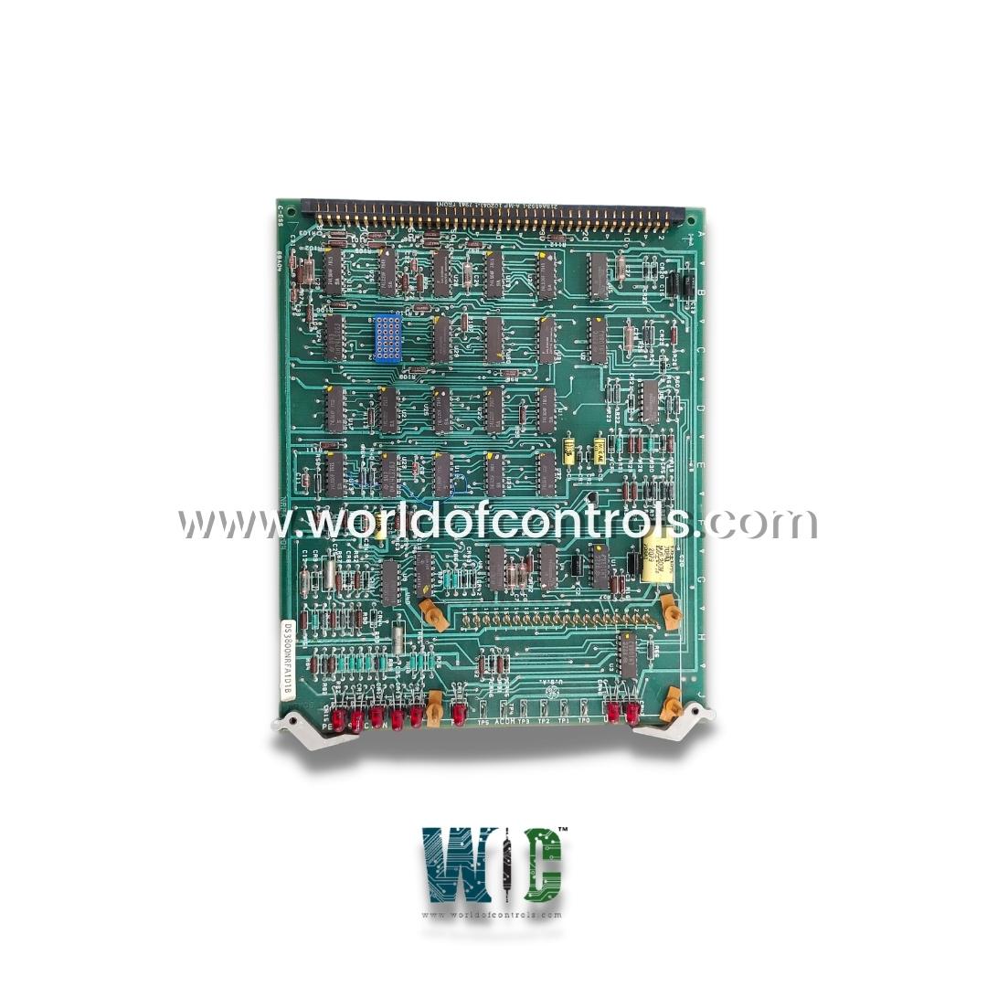
DS3800NRFA1D is a Ramp/Foll Board manufactured and designed by General Electric. It is a Part of Mark IV series. It plays a key role in regulating acceleration and deceleration rates, ensuring smooth transitions in turbine speed and load changes. By managing the rate at which commands are executed, the board helps prevent sudden surges or drops in power, reducing mechanical stress and improving system stability.
Features
- Acceleration and Deceleration Control: Regulates turbine speed during load changes, preventing jerky behavior. Prevents mechanical stress on turbine components by managing the rate of power changes. Enhances system reliability by stabilizing sudden fluctuations that could otherwise cause damage.
- Integration with Optional Auxiliary Board: It acts as the motherboard for the optional auxiliary board. When installed, the main board gains access to two quick-connect screw mounts and six potentiometers for additional control options. The two boards connect via nineteen board-to-board pins, ensuring seamless communication between the boards and enhancing the board's functionality.
- Connector and Mounting Features: Augat connector (female) and PCB mating connector are used for establishing power and data connections, marked 218A4553-1 A/mp. The board is numbered with increments from ten to eighty behind the connector for easy identification. The extractor clips installed on the board's right corners help technicians safely install or extract the board in confined spaces. These clips act as a lever point to handle the board without damaging components or circuits.
- LED Indicators and Test Points: Eight red LEDs are installed for visual diagnostics. Each LED is individually labeled to indicate specific operational statuses or error conditions. There are six test points (TP0 through TP5), with TP4 labeled as ACOM, allowing for real-time monitoring and troubleshooting of the board's circuits and functions.
- Integrated Transistor and Circuitry: The board integrates a transistor designed to support high-speed switching operations. Includes several key logic gates, such as 3-input and 4-input NAND gates, and hex inverter gates. These gates help process the input signals, regulate the ramp and follower functions, and ensure stable and reliable system performance. Various diodes, resistors, and capacitors are embedded within the board. Resistors are made of ceramic-covered metal film, providing stability and protection against heat.
- Acceleration and Deceleration Control: The board ensures that speed or load adjustments occur gradually, preventing sudden shocks to the system.
- Load Following (Foll) Capability: It dynamically adjusts the power output based on demand fluctuations, optimizing performance.
- Integration with Control Systems: Communicates with the main turbine control system, receiving and processing commands for smooth ramp-up and ramp-down operations.
- Protection Against Overloads: Prevents excessive stress on turbine components by moderating power and torque variations.
- Improved System Efficiency: By ensuring gradual transitions, the board helps maintain operational stability and enhances fuel efficiency.
Installation and Maintenance
- Pre-Installation Inspection: Before installing, ensure that the unit is free of physical damage and that all components, including connectors and LEDs, are intact. Inspect the shipping container for any visible damage.
- Installation: Install the board in its designated slot in the Mark IV control system. If the auxiliary board is used, connect it to the motherboard via the nineteen board-to-board pins.
Secure the board using extractor clips to avoid damage during installation.
- Diagnostic Checks: Use the LED indicators to check for any errors or operational issues after installation. Perform system tests using the test points (TP0 - TP5) to monitor voltage levels and ensure proper signal transmission across the board's circuits.
WOC has the largest stock of GE Replacement Parts. WOC is happy to assist you with any of your automation requirements. For pricing and availability on any parts and repairs, kindly get in touch with our team by phone or email.
FREQUENTLY ASKED QUESTIONS
�
What is DS3800NRFA1D?
It�is a Ramp/Foll Board manufactured and designed by General Electric.
What are the LED indicators on the board?
It has eight red LEDs that serve as diagnostic tools. These LEDs are individually labeled to indicate specific errors or operational states. Additionally, the board features a green LED to show normal operation and six test points that allow for real-time diagnostics.
What are the test points on the board used for?
The test points (TP0 - TP5) are used to monitor the voltage levels of various signals on the board. These test points help technicians diagnose issues by providing insight into the health of the board and the overall turbine system.
