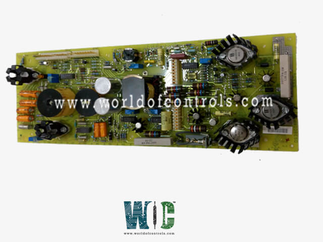
SPECIFICATIONS
Part No.: DS3800NPSU1F1C
Manufacturer: General Electric
Series: Mark IV
Product type: Turbine Control Card
Repair: 3-5 Days
Availability: In Stock
Country of Manufacture: United States (USA)
Functional Description
DS3800NPSU1F1C is a Turbine Control Card developed by GE. It is a part of Mark IV control system. The Mark IV Control System is a sophisticated and highly reliable control system designed for managing gas turbine operations. It integrates advanced control, monitoring, and diagnostic capabilities to optimize turbine performance, ensure safety, and enhance operational efficiency.
Operator Control Switches
- Operation/Control Group: This set of switches allows the operator to manage the primary operations of the gas turbine equipment, enabling various operational commands and adjustments. The operator can start, stop, and modify the operational parameters of the turbine using these controls.
- Emergency Stop Pushbutton: This is a critical safety feature that allows the operator to immediately halt the operation of the gas turbine in case of an emergency. It is designed to be easily accessible and is active in all modes of operation to ensure rapid response during critical situations.
- Alarm Group: This group includes switches that help the operator monitor and respond to alarm conditions, ensuring timely intervention when necessary. The alarm silence and reset functions are part of this group, allowing the operator to acknowledge and clear alarms.
- Display Keypad Group: This group of switches is used to input data into the system, enabling the operator to enter commands and modify settings. The keypad facilitates precise data entry and operational adjustments.
- Display Cursor Group: These switches are used to navigate through various displays and data fields on the operator interface. The cursor controls allow the operator to move within the display screens to access and manipulate different data points.
- Display Mode Group: This group allows the operator to switch between different display modes, providing various views and perspectives of the data. Different modes can offer detailed insights into specific operational parameters or broader overviews of system status.
- Display Functions Group: These switches enable the operator to perform specific functions related to data display, such as zooming in on particular data points, switching between graphs and tables, or accessing detailed reports.
- Printer Group: This set of switches controls the printing functions, allowing the operator to print reports, data logs, and other relevant documents directly from the interface. This is essential for maintaining records and documentation of turbine operations.
- Auxiliary Display Group: These switches provide alternative display options, allowing the operator to view data and control the turbine using auxiliary displays instead of the main CRT (cathode ray tube) display. This ensures redundancy and reliability in data visualization.
World of Controls has the most comprehensive collection of GE Mark IV components. Please contact WOC as soon as possible if you require any extra information.
Frequently Asked Questions
What is DS3800NPSU1F1C?
It is a Turbine Control Card developed by GE
Can the Mark IV Control System display data on auxiliary displays?
Yes, the Auxiliary Display Group within the Operator Interface Module allows the operator to view data and control the turbine using auxiliary displays as an alternative to the main CRT display. This ensures redundancy and reliable data visualization.
Why are certain switches marked with a blue triangle on display?
Certain switches marked with a blue triangle remain functional even when the C Communicator is not operating. These switches include the stop in the Operation/Control group and the Alarm Silence and Alarm Reset switches in the Alarm group, ensuring critical control functions are always available.
