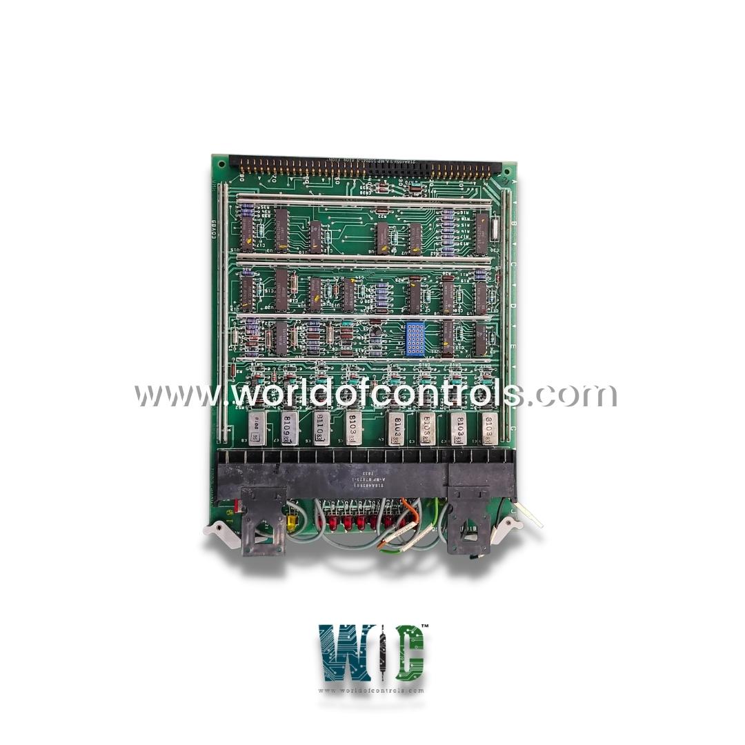
World Of Controls understands the criticality of your requirement and works towards reducing the lead time as much as possible.
DS3800HRRB1B - Relay Output Board is available in stock which ships the same day.
DS3800HRRB1B - Relay Output Board comes in UNUSED as well as REBUILT condition.
To avail our best deals for DS3800HRRB1B - Relay Output Board, contact us and we will get back to you within 24 hours.
Part No.: DS3800HRRB1B
Manufacturer: General Electric
Country of Manufacture: United States(USA)
Product Type: Relay Output Board
Series: Mark IV
DS3800HRRB1B is a Relay Output Board developed by GE. It is a part of Mark IV control system. Relay Output Board is used to interface low-voltage control circuits with high-power electrical devices. It consists of multiple electromechanical or solid-state relays that act as switches, allowing control signals to safely operate heavy loads such as motors, solenoids, and alarms. The board receives input signals from a controller and converts them into electrical outputs that can activate or deactivate connected equipment.
The HRRB1B1A variant is equipped with a total of sixteen EEPROMs and EPROMs, which serve as memory storage components. The EEPROM (Electrically Erasable Programmable Read-Only Memory) allows for encoding only once, making it ideal for storing critical firmware that should not be frequently modified. On the other hand, EPROMs (Erasable Programmable Read-Only Memory) can be encoded multiple times as needed, providing greater flexibility in programming and updating system data.
For status monitoring and diagnostics, the board includes:
These LEDs help indicate different operational states, faults, or system responses. Additionally, the board is equipped with four silver diodes, which regulate electrical flow and provide protection against voltage spikes.
A critical component of the Operator Interface Module, the Auxiliary Display serves as a backup CRT (Cathode Ray Tube) display, located in the upper right corner of the interface panel. This display provides operators with real-time system data and alarm notifications, derived from any of the four control panel computers C, R, S, T. The Auxiliary Display operates in two main modes:
It consists of a digital display, computer status indicators, and two groups of switches. To facilitate its use, an instruction plate with a magnetic backing is included, allowing it to be attached directly to the panel front for quick reference.
Our experts can assist you with your GE Speedtronic Mark IV control requirements at any time. We go above and beyond to ensure our customers' satisfaction. We want your machinery or facility to be operating at peak efficiency. We are here to assist you. If you require any additional information, please contact WOC.
What is DS3800HRRB1B?
It is a Relay Output Board under the Mark IV series.
What memory components does the board contain?
It is equipped with sixteen EEPROMs and EPROMs. Only one EEPROM can be encoded, while EPROMs can be encoded multiple times as required.
What LEDs and indicators are present on the board?
The board features eight white LEDs, eight red LEDs, and one yellow LED, which provide real-time status indications for system monitoring and diagnostics.
How is the board designed for durability and stability?
The board is divided into seven barriers and contains approximately seventy regulators, helping to maintain voltage stability. Additionally, it has four silver diodes for electrical protection and four contact points for secure mounting.