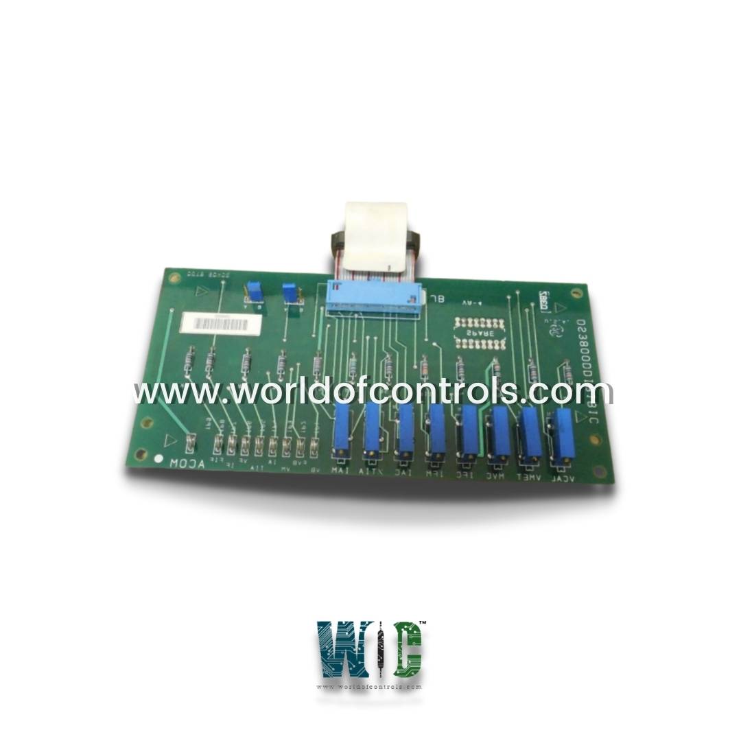
World Of Controls understands the criticality of your requirement and works towards reducing the lead time as much as possible.
DS3800DDIB - Auxiliary Drive Interface Control Board is available in stock which ships the same day.
DS3800DDIB - Auxiliary Drive Interface Control Board comes in UNUSED as well as REBUILT condition.
To avail our best deals for DS3800DDIB - Auxiliary Drive Interface Control Board, contact us and we will get back to you within 24 hours.
SPECIFICATIONS:
Part Number: DS3800DDIB
Manufacturer: General Electric
Series: Mark IV
Product Type: Auxiliary Drive Interface Control Board
Operating temperature: -40°C ~ +85°C
Input Voltage: 4.5-40 VDC
Output Voltage: 1.5-35 VDC
Voltage Differential Required: Output Current: 2A
Switching Frequency: 150kHz
Voltage Regulation: +/- 0.5%
Board Size: 42mm x 20mm x 10mm
Repair: 3-7 Day
Availability: In Stock
Weight: 2 lbs
Country of Origin: United States
FUNCTIONAL DESCRIPTION:
DS3800DDIB is an Auxiliary Drive Interface Control Board manufactured and designed by General Electric as part of the Mark IV Series used in GE Speedtronic Gas Turbine Control Systems. It is an electronic circuit board designed to manage and control the interface between a system and auxiliary drives. This board typically contains various electronic components and circuits that enable communication, data transfer, and control signals between the main system and auxiliary drives. The term "control circuit" suggests that the board is responsible for regulating and directing the operation of the auxiliary drives, ensuring they function in coordination with the overall system. The features of an Auxiliary Drive Interface Control Circuit Board can vary based on the specific application and requirements of the system it's designed for. However, here are some common features that such a board may possess:
WOC maintains the largest inventory of replacement parts for GE Speedtronic control systems. Additionally, we offer warranty-backed unused and rebuilt boards as well as board repairs for your damaged ones. For your OEM needs, our team of professionals is available around the clock. We at WOC are happy to help you with any needs you may have in terms of automation. Please contact our team by phone or email for pricing and availability on any components and repairs.
What is an Auxiliary Drive Interface Control Circuit Board?
An Auxiliary Drive Interface Control Circuit Board is an electronic component that facilitates communication and control between a main system and auxiliary drives. It manages the interface, ensuring coordinated operation and control of the auxiliary drives within a larger system.
What functions does the Control Circuit Board perform?
The board interprets commands from the main system, generates control signals, manages power distribution to the auxiliary drives, monitors their status, and ensures they operate within specified parameters. It essentially acts as an intermediary for seamless integration.
What communication protocols are supported by these boards?
The boards can support various communication protocols such as I2C, SPI, UART, or industry-specific standards, depending on the requirements of the system.