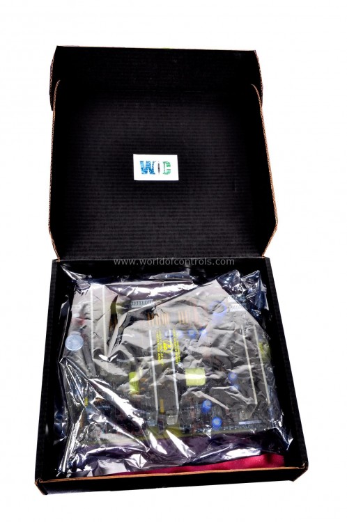
SPECIFICATIONS
Part Number: DS215UCVAG3AD
Manufacturer: General Electric
Series: Mark V
Product type: Unit Controller 2000/VME Board
Country of Manufacture: United States (USA)
Functional Description
DS215UCVAG3AD is a unit controller 2000/VME board developed by GE under Mark V control system. The board contains the processor that replaces the PLC for LCIs using Innovation Series Controllers. When using auxiliary I/O boards with unit controller 2000 module that require IACK and bus grant signals, the empty G3 position (which is not connected to P1) must have those signals jumpered on the backplane.
Standard Hardware
- One IV-486 Board: This board serves as a central processing unit, typically equipped with an Intel 486 microprocessor.
- Two UCVAG1 Boards: These boards function as controller boards, providing necessary interfaces and control signals for the module.
- Two MicroGeni Boards: These boards are designed to enhance the module's capabilities, potentially offering additional processing power or specialized functions for specific applications.
Features
- Slot Occupancy: It occupies four VME slots within a system. All of these slots, except for the third slot from the left, must be equipped with a P1 connector to ensure proper functionality.
- Processor: The module is powered by a 486DX4-100 processor, providing robust computational capabilities.
- DRAM: The module is equipped with 16MB of DRAM, facilitating efficient data processing and storage.
- Flash Memory: It includes 4MB of flash memory for reliable storage of firmware and critical data.
- DLAN+ Ports: There are two DLAN+ ports for advanced local area networking.
- Genius LAN Ports: The module features two Genius LAN ports, enabling connectivity within GE's Genius LAN environment.
- Ethernet Ports: It includes two 10Base2 Ethernet ports, allowing for network connectivity using coaxial cable.
- User Connection Ports: All necessary ports for connecting the module to external devices and networks are located on the faceplate. These ports include DLAN+ ports, Genius LAN ports, and 10Base2 Ethernet ports, ensuring seamless integration with various communication networks and systems.
- Configurable Hardware: The faceplate provides access to hardware configurations that users may need to adjust based on their specific application requirements. This can include switches, jumpers, or other interfaces that allow for customization and optimization of the module's performance.
- LED Indicators: A series of LED indicators are present on the faceplate, offering real-time visual feedback on the module's status and operation. These LEDs can display various states such as power status, network activity, and error conditions, aiding users in monitoring the module's performance and diagnosing issues quickly.
Power Requirements
- +5 V DC: The module requires approximately 3.74 amperes at peak usage. This voltage is essential for the primary operation of the module's digital circuits, including the processor and memory components.
- +12 V DC: The module needs approximately 85 milliamperes at peak usage for this voltage. This is typically used for powering certain analog components or additional circuitry within the module.
- -12 V DC: Similarly, the module requires approximately 85 milliamperes at peak usage for this negative voltage. This is often used in conjunction with the +12 V DC supply to power analog components and provide balanced power to certain subsystems.
Installation
- The component has been mounted in the VME rack. Align the board with the open VME rack slots you intend to install it in and slide it into the rack.
- The connector on the board's back is inserted into the rack's matching connector. To secure the board in the rack, close the retention levers on the board.
WOC is happy to assist you with any of your GE requirements. Please contact us by phone or email for pricing and availability on any parts and repairs.
FREQUENTLY ASKED QUESTIONS
What is DS215UCVAG3AD?
It is a unit controller 2000/VME board developed by GE
What are the LED status indicators on the Board?
It has several LED status indicators including SLOT1, ACTIVE, BACC, ENET, OK, and BERR. The ENET LED is lit when an Ethernet connection is made to a local area network, and it flashes to indicate network activity.
How can you control the GE Unit Controller VME Board?
You can control by connecting a keyboard and monitor to the front connectors on the board. This allows you to access the user interface and tailor the board's operation to the specific needs of your site.
What are the configuration switches used for?
The configuration switches are used to tailor the board's processing activity to the specific needs of your site. You can learn about the switches and how they affect the board's processing activity by consulting the written material that came with the original board.
