SPECIFICATIONS
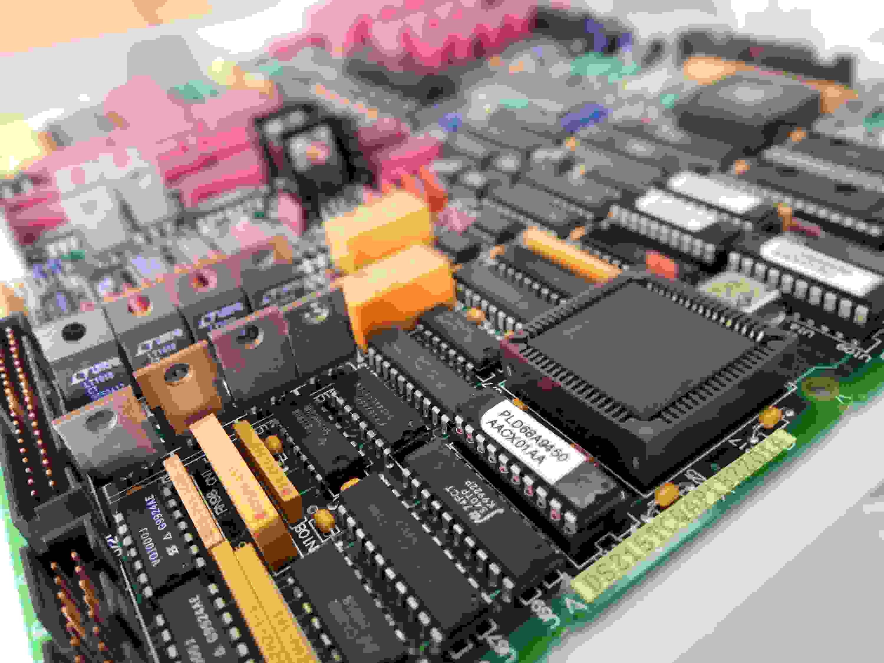
Part No.: DS215TCQAP1BZZ01A
Manufacturer: General Electric
Country of Manufacture: United States of America (USA)
Product Type: Analog I/O Board
Availability: In Stock
Series: Mark V
Functional Description
DS215TCQAP1BZZ01A is an analog I/O board developed by GE. It is a part of Mark V control system. The Analog I/O Boards are responsible for scaling and conditioning a wide array of analog signals that are read by terminal boards mounted on the I/O cores designated as R1, R2, and R3. These signals encompass a variety of inputs and outputs crucial for the operation and monitoring of various systems.
Types of Signals Handled
- LVDT/LVDR Inputs: Linear Variable Differential Transformer (LVDT) and Linear Variable Differential Receiver (LVDR) inputs, which are essential for precise position sensing.
- Servo Valve Outputs: Outputs that control the operation of servo valves, critical for regulating fluid flow in hydraulic systems.
- Thermocouple Inputs: Inputs from thermocouples, which are used for temperature measurement.
- 4-20 mA Inputs and Outputs: Standardized current signals are used for transmitting information over long distances with high noise immunity.
- Vibration Inputs: Signals that monitor vibrations, crucial for detecting imbalances and mechanical failures.
- Relay Driver Outputs: Outputs that drive relays, are used to control high-power devices.
- Pulse Inputs: Digital pulse signals are used for various control and measurement applications.
- Voltage Inputs: Analog voltage signals are used for various sensing and control functions.
- Generator and Line Signals: Signals related to the generator and power lines, are important for electrical power management and monitoring.
Signal Processing and Communication
- Some of these analog signals are transmitted to the STCA board via the 3PL connector. This ensures that the necessary data is shared between the TCQA and STCA boards for further processing and control.
- Generator and line signals are exchanged with the TCQC board through the JE connector. This interaction is crucial for the accurate monitoring and control of electrical parameters in power generation systems.
- Specific 4-20 mA input signals, such as those for fuel flow pressure and compressor stall detection, are scaled and conditioned directly on the TCQA board. This processing ensures that the signals are within the appropriate range and format for further use in the control system.
Jumper Configurations
- J1 and J2: These jumpers are used to select the milliamp output circuits. By configuring J1 and J2, you can choose which specific circuits are active for the milliamp outputs, allowing for tailored signal processing and output.
- J5 and J6: These jumpers are crucial for setting the current range of the milliamp outputs. Depending on the requirements of your application, you can configure:
- 20 mA Maximum: By setting J5 and J6 accordingly, the milliamp output will be limited to a maximum of 20 mA, suitable for standard control signals.
- 200 mA Maximum: Alternatively, you can configure J5 and J6 to allow for a maximum output of 200 mA, which is necessary for applications requiring higher current levels.
- J7: This jumper is associated with the RS232 port and is primarily used for card tests. By configuring J7, you enable the RS232 port, which facilitates communication and diagnostic testing of the board, ensuring it functions correctly and efficiently.
- J8: This jumper is used to enable an oscillator. The oscillator is a critical component for generating precise timing signals necessary for various operations on the board. Enabling it through J8 ensures that the board's timing functions are accurate and reliable.
The WOC team is always available to help you with your Mark V requirements. For more information, please contact WOC.
Frequently Asked Questions
What is DS215TCQAP1BZZ01A?
It is an analog I/O board developed by GE under the Mark V series.
What is the purpose of jumpers J1 and J2 on the board?
Jumpers J1 and J2 are used to select the milliamp output circuits. By configuring these jumpers, you can choose which specific circuits are active for the milliamp outputs, allowing for tailored signal processing and output.
What is the function of jumper J7?
Jumper J7 is associated with the RS232 port and is primarily used for card tests. By configuring J7, you enable the RS232 port, facilitating communication and diagnostic testing of the board to ensure it functions correctly and efficiently.
What role does jumper J8?
Jumper J8 is used to enable an oscillator. The oscillator is a component for generating precise timing signals necessary for various operations on the board. Enabling it through J8 ensures that the board's timing functions are accurate and reliable.
