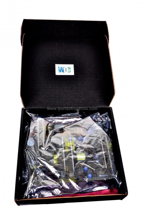
World Of Controls understands the criticality of your requirement and works towards reducing the lead time as much as possible.
DS215GGIAG1BZZ01B - Exciter Voltage Regulator Module is available in stock which ships the same day.
DS215GGIAG1BZZ01B - Exciter Voltage Regulator Module comes in UNUSED as well as REBUILT condition.
To avail our best deals for DS215GGIAG1BZZ01B - Exciter Voltage Regulator Module, contact us and we will get back to you within 24 hours.
SPECIFICATIONS:
Part Number: DS215GGIAG1BZZ01B
Manufacturer: General Electric
Series: EX2000
Product Type: Exciter Voltage Regulator Module
Number of channels: 12
Input voltage: 125 - 400 VDC
Nominal power: up to 1000 W
Input auxiliary voltage: up to 20 V DC
Operating temperature: -30 to 55 degrees Celsius
Size: 8.25 cm high x 4.18 cm
Repair: 3-7 Day
Availability: In Stock
Weight: 2 lbs
Country of Origin: United States
FUNCTIONAL DESCRIPTION:
DS215GGIAG1BZZ01B is an Exciter Voltage Regulator Module manufactured and designed by General Electric as part of the EX2000 Series used in GE Excitation Gas Turbine Control Systems. The firmware that powers this board is a testament to GE's commitment to innovation, ensuring that the board effectively translates digital instructions into tangible actions, enabling efficient control, monitoring, and coordination of processes. It facilitates the flow of information, commands, and data across the system, acting as a bridge between various subsystems and components. Through this role, the board enables the system to maintain precise regulation, enhance stability, and optimize performance, all while adhering to the highest standards of safety and reliability.
FEATURES:
PRODUCT ATTRIBUTES:
WOC maintains the largest inventory of Replacement parts for GE Excitation control systems. Additionally, we offer warranty-backed unused and rebuilt boards as well as board repairs for your damaged ones. For your OEM needs, our team of professionals is available around the clock. We at WOC are happy to help you with any needs you may have in terms of automation. Please contact our team by phone or email for pricing and availability on any components and repairs.
What are self-test diagnostics in the EX2000 exciter software?
Self-test diagnostics are built-in features within the EX2000 exciter software that allow the system to automatically check its own functionality and identify potential faults or issues.
How does the self-test diagnostic system work?
The self-test diagnostic system within the EX2000 exciter software conducts automated tests on various system components. If a fault is detected, the system generates fault codes that indicate the nature of the issue.
What is the purpose of displaying fault codes on both the programmer's display and the LDCC board's LEDs?
The dual display of fault codes provides redundancy and backup in case one display method becomes unreadable or unavailable. It ensures that operators can quickly identify faults and initiate troubleshooting, even in challenging situations.