SPECIFICATIONS
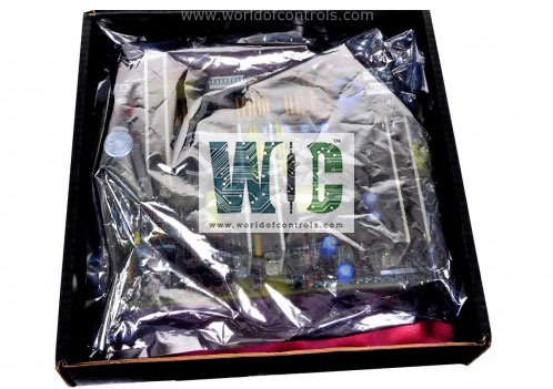
Part No.: IS230TRLY2EG01
Manufacturer: General Electric
Country of Manufacture: United States of America (USA)
Size: 33.0 cm high x 17.8 cm, wide
Technology: Surface mount
Temperature: -30 to 65oC
Product Type: Relay Output Terminal Board
Availability: In Stock
Series: Mark VIe
Functional Description
IS230TRLY2EG01 is a relay output terminal board developed by GE. It is a part of the Mark VIe control system. It serves as a relay output terminal board designed for integration with the contact input/relay output board VCCC within the control system. This component plays a crucial role in relay functionality and system operation.
Features
- Relay Configuration with VCCC Model: When the board is utilized alongside the VCCC model, it's important to note that two TRLY models are required to achieve a total of 24 relays. This configuration ensures comprehensive relay control and management within the system architecture.
- Simplex Application Type: In simplex application scenarios, the cables connected to the model serve a dual purpose. They carry both control signals and monitor feedback voltages between the TRLY and VCCC through the JA1 connector. This integrated communication mechanism enhances system reliability and performance.
- Versatile Relay Circuit Configurations: Flexibility in relay circuit configurations. Users can jumper configure several relay circuits to function as Form-C contact outputs, drive external solenoids for actuation purposes, or serve as dry outputs for signaling, depending on specific application requirements.
- Triple Modular Redundant (TMR) Applications: In TMR applications, the relay control signals are distributed from the three attached VME board racks T, R, and S via the JT1, JR1, and JS1 plugs, respectively. This distributed approach ensures redundancy and fault tolerance, enhancing system resilience in critical operational environments.
Operation
- The board is equipped with essential components such as relay drivers, fuses, and jumpers, all of which play critical roles in the operation of the system. Relay drivers are responsible for controlling the relays, which act as switches to control high-power devices using low-power signals. These drivers ensure that the relays are activated or deactivated based on the control signals they receive, allowing the system to manage various electrical loads effectively.
- Fuses are incorporated to provide protection against overcurrent conditions. They act as safety devices that prevent excessive current from damaging the circuitry or connected devices. If an overcurrent situation arises, the fuse will blow, interrupting the circuit and protecting the system from potential damage.
- Jumpers allow for configurable settings. These small connectors can be placed in different positions to open or close circuits, enabling users to customize certain operational parameters of the board according to specific needs or requirements.
- For simplex operation, which involves a single channel of communication without redundancy, D-type connectors are utilized to facilitate the connection between the I/O processors and the TRLY board. These connectors are robust and reliable, ensuring secure and stable connections for transmitting control signals and monitoring feedback voltages.
- The control signals and feedback voltages are carried through the JA1 connector. This connector plays a vital role in the communication process, ensuring that the I/O processors can send and receive accurate signals to and from the board. The control signals determine the actions of the relay drivers, while the feedback voltages provide essential information about the status and performance of the relays and other components.
Fault Detection
In the operation of the model, various fault detection mechanisms are in place to ensure system integrity and reliability. These mechanisms are designed to promptly identify and respond to potential issues, minimizing the risk of operational disruptions.
- Loss of Relay Solenoid Excitation Current: One crucial fault detection mechanism involves monitoring the solenoid excitation current of the relays. In the event of a loss of excitation current, indicating a potential fault or malfunction in the relay system, it is equipped to detect this anomaly and trigger appropriate response actions.
- Coil Current Disagreement with Command: Another critical aspect of fault detection is ensuring that the actual coil current of the relays aligns with the commanded values. Any disagreement between the commanded coil current and the actual measured current can indicate a fault in the relay operation. Continuously monitors this parameter to detect discrepancies and initiate corrective measures as necessary.
- Unplugged Cable or Loss of Communication with the I/O Board: Incorporates mechanisms to detect unplugged cables or loss of communication with the associated I/O board. If communication with the I/O board is interrupted or if an unplugged cable is detected, the relays are programmed to de-energize as a safety precaution. This proactive approach helps prevent potential hazards or malfunctions that may arise from communication disruptions or cable disconnections.
The WOC team is always available to help you with your Mark VIe requirements. For more information, please contact WOC.
Frequently Asked Questions
What is IS230TRLY2EG01?
It is a relay output terminal board developed by GE under the Mark VIe series.
What are the functions of jumpers JP1 through JP12?
Jumpers JP1 through JP12 are utilized for various purposes, including contact voltage sensing. When contact voltage sensing is necessary for specific relays, users can insert jumpers for the selected relays to enable this functionality.
What is the role of fuses FU1 through FU12?
Fuses FU1 through FU12 play a crucial role in providing power to the relays. Specifically, if power is required for relays 1-6, it is recommended to place two fuses in each power circuit supplying those relays. This ensures proper protection and distribution of power to the relay circuits.
