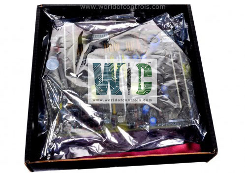
IS230TRLY1BG01 - Relay Output Assembly Module

IS230TRLY1BG01 - Relay Output Assembly Module IS230TRLY1BG01 - Relay Output Assembly Module

World Of Controls understands the criticality of your requirement and works towards reducing the lead time as much as possible.

IS230TRLY1BG01 - Relay Output Assembly Module is available in stock which ships the same day.

IS230TRLY1BG01 - Relay Output Assembly Module comes in UNUSED as well as REBUILT condition.

To avail our best deals for IS230TRLY1BG01 - Relay Output Assembly Module, contact us and we will get back to you within 24 hours.

SPECIFICATIONS

Part No.: IS230TRLY1BG01
Manufacturer: General Electric
Country of Manufacture: United States of America (USA)
Size: 17.8 cm wide x 33.02 cm high
Temperature: -30 to + 65oC (-22 to +149 oF)
Product Type: Relay Output Assembly Module
Availability: In Stock
Series: Mark VI

Functional Description

IS230TRLY1BG01 is a Relay Output Assembly Module developed by GE. It is a part of Mark VI control system.

Relay Configuration

The terminal board accommodates 12 plug-in magnetic relays.
The first six relay circuits are configurable via jumpers to support either dry contact outputs, Form-C contact outputs, or to drive external solenoids.
Jumper configurations allow flexibility in adapting the relay circuits to specific application requirements.

Power Supply Options

  • The board supports a standard 125 V dc or 115/230 V ac power source for operation.
  • Additionally, an optional 24 V dc power source is available, with individual jumper-selectable fuses and on-board suppression for enhanced safety and protection.
  • Field solenoid power can be provided from the available power sources, ensuring compatibility with various system setups.

Relay Functionality

  • Relays 1 to 6 are configured to provide either dry contact outputs, Form-C contact outputs, or to drive external solenoids based on jumper configurations.
  • Relays 7 to 11 are isolated Form-C contacts, offering versatile connectivity options for different system components.
  • Output 12 is an isolated Form-C contact specifically designated for special applications, such as ignition transformers, providing tailored functionality as needed.

Application Flexibility

  • The terminal board's configurable relay circuits and power supply options offer versatility to accommodate a wide range of industrial applications.
  • Whether it's driving external solenoids, providing isolated contacts, or supporting special applications like ignition transformers, it offers tailored solutions to meet diverse requirements.

Enhanced Safety and Protection

  • The inclusion of jumper-selectable fuses and on-board suppression ensures enhanced safety and protection against electrical surges and faults.
  • These features contribute to the reliability and durability of the terminal board, minimizing the risk of damage or malfunction during operation.

Other Features

  • Response Time: Maximum response time on: 25 ms (typical), Maximum response time off: 25 ms (typical)
  • Maximum Inrush Current: 10 A, The terminal board can handle a maximum inrush current of 10 A, allowing it to withstand temporary surges during operation.
  • Contact Material: Silver cad-oxide, The relay contacts are made of silver cad-oxide, known for its excellent conductivity and durability, ensuring reliable performance over an extended lifespan.
  • Fault Detection: Loss of relay solenoid excitation current, Coil current disagreement with command, Unplugged cable or loss of communication with I/O board, The terminal board incorporates advanced fault detection mechanisms to identify and respond to potential issues promptly, ensuring system integrity and minimizing downtime.

The WOC team is always available to help you with your Mark VI requirements. For more information, please contact WOC.

Frequently Asked Questions

What is IS230TRLY1BG01?
It is a relay output assembly module developed by GE under the Mark VI series.

What are jumpers JP1-JP6, and why are they removed in the factory?
Jumpers JP1-JP6 are electrical connectors that serve various functions within the system. They are removed in the factory and shipped separately in a plastic bag as a precautionary measure. This allows for flexibility in configuring the system based on specific requirements and ensures safe transportation of the equipment.

When should jumpers be re-installed, and why?
Jumpers should be re-installed when power to a field solenoid is required. These jumpers establish the necessary electrical connections to enable the operation of field solenoids within the system.

How should jumpers be re-installed?
To re-install jumpers, carefully refer to the system documentation or schematic diagrams to determine the appropriate jumper configuration based on the specific requirements of the application. Follow standard practices for jumper installation, ensuring proper alignment and secure connections.