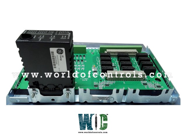
World Of Controls understands the criticality of your requirement and works towards reducing the lead time as much as possible.
IS230TDBTH6AA - Contact Input/Relay Output Terminal Board is available in stock which ships the same day.
IS230TDBTH6AA - Contact Input/Relay Output Terminal Board comes in UNUSED as well as REBUILT condition.
To avail our best deals for IS230TDBTH6AA - Contact Input/Relay Output Terminal Board, contact us and we will get back to you within 24 hours.
SPECIFICATIONS:
Part Number: IS230TDBTH6AA
Manufacturer: General Electric
Series: Mark VIe
Product Type: Contact Input/Relay Output Terminal Board
Number of input channels: 24
Number of relay channels: 12
Input Current: 24 V dc
Trip Solenoid Rating: 125 V dc
Span: -8 mV to +45 mV
AC voltage rejection: 12 V rms
Power supply voltage: 28 V dc
Voltage Range: 18 - 32 VDC
Technology: Surface mount
Operating temperature: 30 to -65°C
Size: 17.8 cm wide x 33.02 cm high
Repair: 3-7 Day
Availability: In Stock
Country of Origin: United States
Manual: GEH-6721D
FUNCTIONAL DESCRIPTION:
IS230TDBTH6AA is a Contact Input/Relay Output Terminal Board manufactured and designed by General Electric as part of the Mark VIe Series used in GE Distributed Control Systems. The TDBT board is a TMR contact input/output terminal board that can be mounted on a DIN rail or directly on a flat surface. It supports 24 group-isolated contact inputs, which receive a nominal 24, 48, or 125 V DC wetting voltage from an external source. The inputs feature noise suppression to protect against surges and high-frequency interference. Additionally, the TDBT provides 12 form-C relay outputs and can accommodate an optional expansion card to enhance relay functions.
In Mark VIe systems, the PDIO I/O pack interfaces with the TDBT. Three I/O packs connect through D-type connectors and communicate with the controllers via Ethernet. There are three connection points for the PDIO. In configurations with dual controllers, the PDIO on the TDBT’s JR1 connector is linked to the R controller, the JS1 PDIO connects to the S controller, and the JT1 PDIO is shared between both controllers. For TMR controllers, each PDIO has a dedicated network connection to its respective controller. The TDBT is not intended to function properly with just a single PDIO I/O pack.
INSTALLATION:
The TDBT, along with a plastic insulator, is mounted onto a sheet metal carrier, which is then affixed to a DIN rail. Alternatively, the TDBT with the insulator can be mounted on a sheet metal assembly that is bolted inside a cabinet. Connections are made directly to two groups of 48 terminal blocks, usually using #18 AWG wires. The upper terminal block set, TB1, is linked to the relay section of the board, while the lower set, TB2, connects to the contact input circuits. The screw configuration for both terminal blocks matches that of the SRLY relay board and the STCI contact input terminal board. Shields should be grounded to a separate bracket.
OPERATION:
The contact input function and onboard signal conditioning on the TDBT are identical to those on the STCI, designed to handle 24, 48, and 125 V DC wetting voltages. The acceptable input voltage ranges are 16 to 32 V DC, 32 to 64 V DC, and 100 to 145 V DC, with the threshold voltage set at 50% of the wetting voltage. The contact sensing circuits are detailed in the I/O pack description. Input currents are limited by resistance, with the first 21 circuits drawing 2.5 mA, and circuits 22 through 24 drawing 10 mA. The 24 V DC supply on TDBTH2 is current-limited to 0.5 A using polymer positive temperature coefficient (PTC) fuses, which are resettable.
Each input is equipped with filters that minimize high-frequency noise and suppress surges near the signal entry point. The discrete voltage signals are sent to the I/O processor, where they pass through optical isolators, are converted to digital signals, and are then transmitted to the controller.
WOC has the largest stock of OEM replacement parts for GE Distributed Turbine Control systems. We can also repair your faulty boards and supply unused and rebuilt boards backed up with a warranty. Our team of experts is available round the clock to support your OEM needs. Our team of experts at WOC is happy to assist you with any of your automation requirements. For pricing and availability on any parts and repairs, kindly contact our team by phone or email.
What is the TDBT board used for?
The TDBT board is designed for contact input/output functions within TMR control systems, providing 24 isolated contact inputs and 12 form-C relay outputs. It is used in Mark VIe systems and supports various wetting voltage options (24, 48, or 125 V DC).
How are the relay outputs connected?
The TDBT board provides 12 form-C relay outputs that can be connected directly via terminal blocks to external circuits. The terminal connections are compatible with the SRLY relay board and the STCI contact input terminal board.
How are the contact input signals processed on the TDBT board?
The contact input signals are processed by filters to suppress noise and surges. They are then sent to the I/O processor, where they are converted to digital signals via optical isolators before being transferred to the controller.