World Of Controls understands the criticality of your requirement and works towards reducing the lead time as much as possible.
IS230PCAAH1BB - Power Connect Card is available in stock which ships the same day.
IS230PCAAH1BB - Power Connect Card comes in UNUSED as well as REBUILT condition.
To avail our best deals for IS230PCAAH1BB - Power Connect Card, contact us and we will get back to you within 24 hours.
SPECIFICATIONS:
Part Number: IS230PCAAH1BB
Manufacturer: General Electric
Series: Mark VIe
Product Type: Power Connect Card
Number of Input channels: 24
Power supply voltage: 28V dc
Technology: Surface Mount
Operating temperature: -30 to 65 °C
Size: 33.02 cm high x 17.8 cm
Repair: 3-7 Day
Availability: In Stock
Country of Origin: United States
Manual: GEI-100161B
FUNCTIONAL DESCRIPTION:
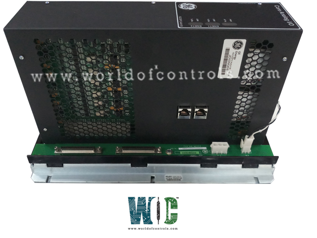
IS230PCAAH1BB is a Power Connect Card manufactured and designed by General Electric as part of the Mark VIe Series used in GE Distributed Control Systems. The DS200PCCA Power Connect Card (PCCA) interfaces the drive’s control circuitry and the SCR power bridge. The PCCA board uses pulse transformers to provide a gate drive to the SCR bridge. The PCCA board also includes snubber circuits to control spikes across the ac lines, dc bus, and gate drivers for low-to-medium horsepower controllers. For higher horsepower controllers, some or all of the snubber circuits are omitted from the PCCA board and are located elsewhere in the system. The Core Analog (PCAA) Module and Optional Core Analog (TCAT) Terminal Board facilitate analog signal input/output operations within a gas turbine system. The PCAA and TCAT modules encompass a comprehensive array of functionalities, including thermocouple inputs, 4-20 mA current loop I/O, seismic inputs, Linear Variable Differential Transformer (LVDT) excitation and inputs, pulse rate inputs, and servo coil outputs. The PCAA module is adaptable to both simplex and Triple Modular Redundant (TMR) systems, ensuring versatile applicability across different operational setups.
BOARD GROUPS:
The PCCA board has ten group numbers. The group number used in a system is determined by the system voltage, frame size, and whether the system uses regenerative or non-regenerative power conversion. The armature voltage scaling depends on which PCCA board group number is used:
• G1, G7, G9 – Regenerative, 240 – 630 volts
• G2, G8, G10 – Non-regenerative, 240 – 700 volts
The PCCA board has four wire jumpers, designated JP1, JP2, WP3, and WP4 that select system voltage and determine snubber capacitor connections.
CONFIGURABLE JUMPERS (JP and WP):
Jumpers JP1 and JP2 must be connected to the appropriate stab terminals P3 through P10, as determined by the card group number and system voltage. Jumpers WP3 and WP4 are used to connect stab terminals P2A to P2B, and P1A to P1B, respectively. These jumpers are used to select whether the PCCA snubber capacitors are connected to the same point on the power bridge as the voltage feedback channel.
BOARD CONNECTORS:
The PCCA board sends forward and reverse gate pulse signals to the SCR bridge via twelve plug connectors, 1RPL − 6RPL and 1FPL − 6FPL, and communicates with the power supply board via one additional plug connector, 5PL.
WOC has the largest stock of GE Distributed control systems OEM replacement parts. We can also repair your faulty boards and supply unused and rebuilt boards backed up with a warranty. Our team of experts is available round the clock to support your OEM needs. Our team of experts at WOC is happy to assist you with any of your automation requirements. For pricing and availability on any parts and repairs, kindly get in touch with our team by phone or email.
What checks are performed during the power-up self-test?
During the power-up self-test, the system conducts checks on various components including RAM, flash memory, Ethernet ports, and most of the processor board hardware to ensure proper functioning and readiness for operation.
How are internal power supplies monitored?
The system continuously monitors the internal power supplies to verify correct operation, ensuring stable and reliable power distribution throughout the system.
How does the system ensure hardware compatibility and application code correctness?
The system verifies electronic ID information from terminal boards, acquisition boards, and processor boards to confirm hardware compatibility. It then checks the application code loaded from flash memory to ensure it matches the hardware set, thereby ensuring proper system configuration and functionality.
What criteria determine the health of 4-20 mA analog inputs?
The system defines a specified high and low current range for valid signals from the 4-20 mA analog inputs. If a signal falls outside this range, it is deemed to be of poor health.