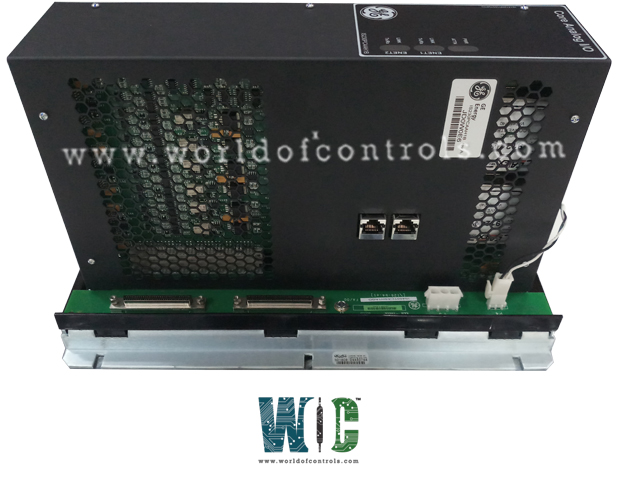
World Of Controls understands the criticality of your requirement and works towards reducing the lead time as much as possible.
IS230PCAAH1A REV A - PCCA Core Analog Module is available in stock which ships the same day.
IS230PCAAH1A REV A - PCCA Core Analog Module comes in UNUSED as well as REBUILT condition.
To avail our best deals for IS230PCAAH1A REV A - PCCA Core Analog Module, contact us and we will get back to you within 24 hours.
SPECIFICATIONS:
Part Number: IS230PCAAH1A REV A
Manufacturer: General Electric
Series: Mark VIe
Product Type: PCCA Core Analog Module
Technology: Surface Mount
Thermocouple types: E, J, K, S, T
Number of Channels: 12
Span: -8 mV to +45 mV
Common Mode Voltage Range: ±5 V
Dimensions: 11.00 x 9.00 x 3.00
Operating temperature: 0 to 60 °C
No.of Analog Voltage Inputs: 6
Repair: 3-7 Day
Availability: In Stock
Country of Origin: United States
Manual: GEH-6721G
FUNCTIONAL DESCRIPTION:
IS230PCAAH1A REV A is a PCCA Core Analog Module manufactured and designed by General Electric as part of the VIe Series used in GE Distributed Gas Turbine Control Systems. The Core Analog (PCAA) module and associated Core Analog (TCAS and TCAT) terminal board provide a large portion of the analog signal I/O required to operate a gas turbine. PCAA and TCAT provide thermocouple inputs, 4-20 mA current loop I/O, seismic inputs, Linear Variable Differential Transformer (LVDT) excitation and inputs, pulse rate inputs, and servo coil outputs. PCAA may be applied in simplex, dual, and TMR systems. A single TCAT terminal board fans signal inputs to one, two, or three connected PCAA modules. The shield ground and 24 V field power terminals on an adjacent JGPA board supplement the terminals on PCAA and TCAT.
PCAA contains a processor board common to all Mark VIe distributed I/O, two application I/O boards, and a terminal board. The complete module is regarded as the least replaceable unit and there is no support provided to diagnose or replace the individual boards making up the module. Input to the module is through dual RJ45 Ethernet connectors and 28 V dc power connector P5. Field device I/O is through 120 euro-style box terminals on the module edge. Power for a JGPA board is through connector P4. Module connection to TCAT is through two 68-pin cables on connectors P1 and P2.
INSTALLATION:
OPERATION:
The PCAA module consists of four separate circuit boards in a single physical assembly. The module is regarded as the least replaceable unit because of the difficulty of isolating a failure to a single board. The module is not designed for the replacement of individual boards. TCAS accepts bulk 28 V control power through the P5 connector. It then provides the power through connector P4 to a JGPA board in the input cable shield termination location. TCAS provides the P1 and P2 68-pin connectors for IS200TCAT terminal board cables. Internal to the module the TCAS terminal board routes signals to connectors for the BCAA and BCAB analog processing boards.
PCAA PROCESSOR:
WOC has the largest stock of Replacement parts for GE Distributed Turbine Control Systems. We can also repair your faulty boards and supply unused and rebuilt boards backed up with a warranty. Our team of experts is available round the clock to support your OEM needs. Our team of experts at WOC is happy to assist you with any of your automation requirements. For pricing and availability on parts and repairs, kindly contact our team by phone or email.
What is the primary function of the PCCA Core Analog Module?
The PCCA Core Analog Module provides the analog signal I/O required for operating gas turbines. It works with terminal boards like TCAS and TCAT to handle thermocouple inputs, current loop I/O, seismic inputs, LVDT excitation, pulse rate inputs, and servo coil outputs.
How is the module connected to the TCAT terminal board?
The module is connected to the TCAT terminal board using two 68-pin cables via connectors P1 and P2. Proper grounding and cable attachment are essential for ensuring signal integrity.
How are Ethernet connections configured for the module?
The module has two independent 10/100 Ethernet ports. It supports both single and dual Ethernet configurations. In TMR systems, the Ethernet connections should correspond to the R, S, or T controller networks.