SPECIFICATIONS
Part No.: IS230JPDS1AG01
Manufacturer: General Electric
Country of Manufacture: United States of America (USA)
Temperature: -30 to +65 oC
Agency approval: Class 1 Division 2 explosive atmosphere
Size: 16.51 cm high x 17.8 cm wide
Mounting: DIN-rail mounting
Product Type: Power Distribution Board
Availability: In Stock
Series: Mark VIe
Functional Description
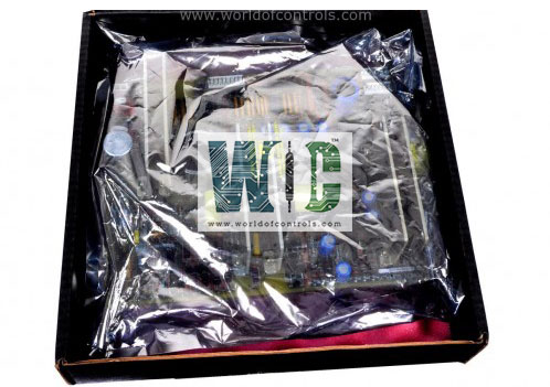
IS230JPDS1AG01 is a power distribution board developed by GE. It is a part of Mark VIe control system. JPDS receives a 28 V DC input power from external AC/DC or DC/DC converters. This input power is then distributed to various components within the control system. It is an integral part of the power distribution system, and it ensures that power is efficiently and reliably provided to the control system.
Features
- One of the key features of the JPDS is its integration with the PDM system, allowing it to offer feedback through the PPDA I/O pack. This feedback mechanism helps in monitoring and managing the power distribution within the system, ensuring optimal performance and reliability.
- The board is designed to be compatible with the feedback signal P1/P2 connectors on several other components, including the JPDB, JPDF, and JPDE. This compatibility ensures seamless integration and communication between these components and the I/O pack.
- Additionally, it features a DC-62 connector, which is compatible with the I/O pack. This compatibility allows for easy connection and communication between the JPDS and PPDA, facilitating efficient power distribution and feedback within the control system.
Physical Arrangement
- The board is designed to accept power from external cables and efficiently distribute it to various connectors, specifically the JR, JS, and JT connectors. This configuration ensures that power is appropriately allocated to different parts of the control system.
- When the JPDS is equipped with a I/O pack, it is mounted in a manner that allows the indicator lights on the PPDA I/O pack to be easily visible. This visibility is crucial for monitoring and diagnosing the status and performance of the PPDA I/O pack.
- In scenarios where two boards are used in tandem, they are mounted strategically to ensure that any terminal board connections remain easily accessible. This arrangement facilitates maintenance and troubleshooting, as technicians can readily access and manage the connections without obstructing each other.
- The placement within a control panel is flexible, as its exact location is not critical to its function. However, care should be taken to ensure that the placement does not impede accessibility or visibility of important indicators and connections.
- Connector P1 on the JPDS plays a vital role in transmitting feedback signals to a board hosting a I/O pack. This feedback is essential for the effective monitoring and control of the power distribution system. Connector P2, on the other hand, receives feedback from other power distribution boards and passes these signals out through P1 to the PPDA. This two-way communication ensures that the control system receives accurate and timely information about the power distribution status.
- When planning to connect a feedback cable from P2 to another power distribution board, careful consideration must be given to the routing of the feedback cable. Proper routing ensures that the feedback signals are transmitted efficiently and without interference, maintaining the integrity and reliability of the power distribution system.
Application Notes
- Independent and Combined Buses: Each of the three independent power buses is sized to handle a current of up to 25 A. This capacity ensures that the buses can support a significant load without risking overload or failure. When combined into a single internal bus, the total capacity is effectively increased, providing a robust power distribution solution for higher current requirements.
- Common Ground: The power buses share a common ground that is sized to handle a total of 75 A. This common ground is crucial for ensuring the safe and efficient operation of the power distribution system. By having a shared ground, JPDS can maintain stability and reduce the risk of electrical faults or interference between the buses.
- Redundancy and Reliability: The design allows for the operation of R, S, and T controllers and their respective I/O from separate power supplies. This separation enhances the system's reliability by ensuring that the failure of one power supply only affects one controller and its I/O, without impacting the other two channels. This redundancy is critical for maintaining continuous operation and avoiding complete system failure in the event of a power supply issue.
- Diode-OR Power Output: To further enhance reliability, the JPDS includes a dedicated 28 V DC diode-OR power output for the PPDA I/O pack. This diode-OR configuration ensures that the PPDA I/O pack continues to receive power even if there is a failure in one of the channel power supplies. By maintaining power to the PPDA I/O pack, the system can avoid losing power system feedback, which is essential for monitoring and managing the overall power distribution.
The WOC team is always available to help you with your Mark VIe requirements. For more information, please contact WOC.
Frequently Asked Questions
What is IS230JPDS1AG01?
It is a power distribution board developed by GE under the Mark VIe series.
What is the purpose of the internal wiring configuration?
The internal wiring configuration allows for either three independent 28 V DC power buses or a single combined internal bus. This flexibility ensures the system can adapt to various power distribution needs and scenarios.
How much current can each independent power bus handle?
Each independent power bus is sized to handle up to 25 A, providing a robust solution for supporting significant electrical loads without risking overload.
What is the total capacity of the common ground shared by the power buses?
The common ground shared by the power buses is sized to handle a total of 75 A, ensuring safe and efficient operation while reducing the risk of electrical faults or interference.
