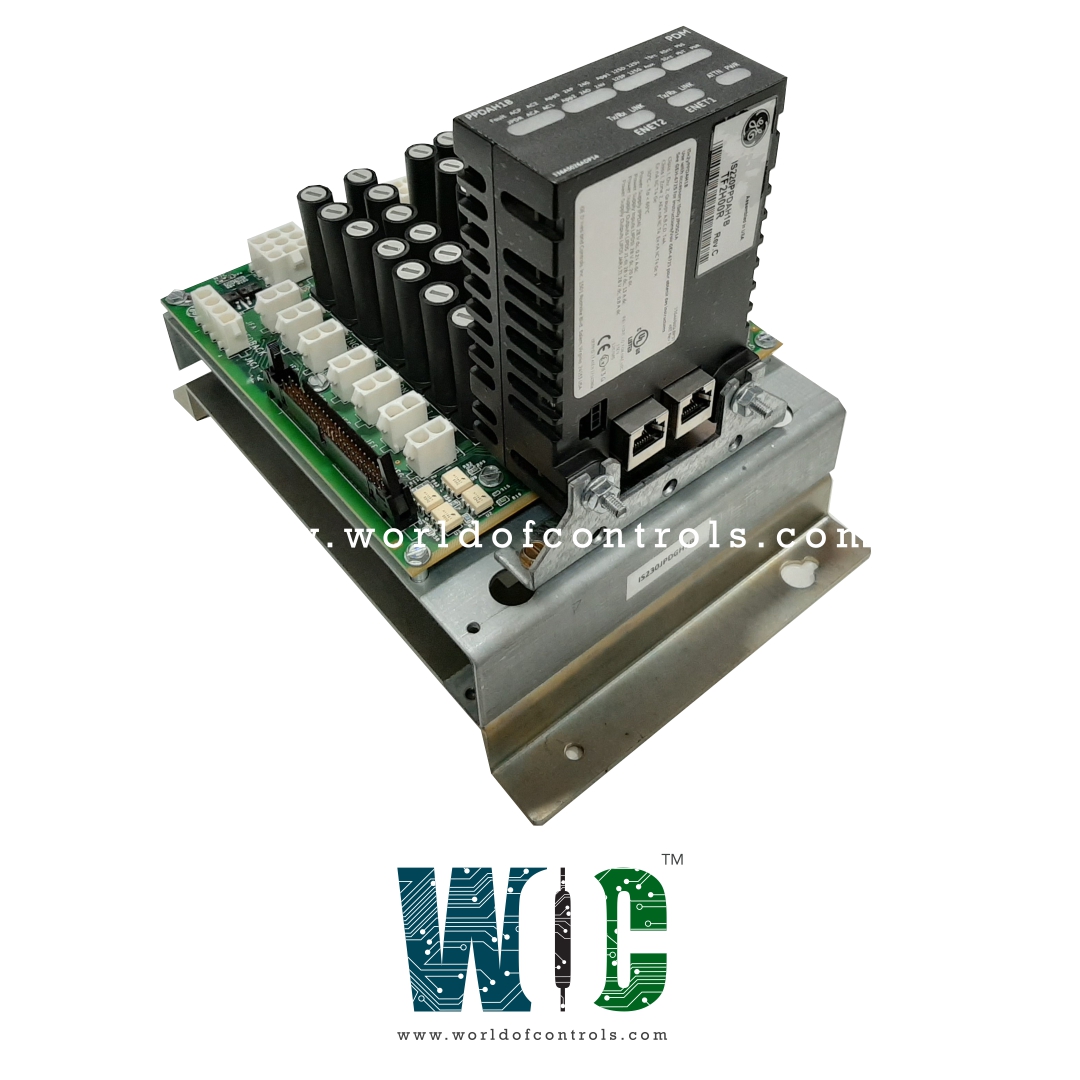
SPECIFICATIONS
Part No.: IS230JPDGH1A
Manufacturer: General Electric
Country of Manufacture: United States of America (USA)
Size: 17.8 cm wide x 33.02 cm high
Temperature: -30 to + 65oC
Technology Surface-mount
Product Type: Power Distribution Module
Availability: In Stock
Series: Mark VIe
Functional Description
IS230JPDGH1A is a Power Distribution Module developed by GE. It is a part of Mark VIe control system. The Power Distribution board serves as a vital component within the control system, facilitating the distribution of power to various boards. It operates with three main power outputs: 28 V DC for control power and 48 V / 24 V DC for wetting power. Additionally, it incorporates sensing circuitry for monitoring two channels of AC distribution.
Features
- The 28 V DC distribution section of the JPDG board is engineered to accommodate two distinct power supply inputs through external diodes. This feature enhances redundancy and reliability in power supply, ensuring uninterrupted operation even in the event of a power source failure.
- Integration with the PPDA I/O pack allows seamless incorporation into the PDM system feedback loop, enabling efficient communication and feedback mechanisms within the control system.
- Moreover, the board offers support for sensing and diagnostics for two AC signals, extending its functionality beyond power distribution. These AC signals are distributed externally from the board, providing comprehensive monitoring and diagnostic capabilities throughout the control system architecture.
Compatibility
- The board boasts versatile capabilities, including the ability to host a Power Distribution System Feedback (PPDA) I/O pack commonly employed in Mark VIe Control Power Distribution Modules. Additionally, it serves as a central hub for receiving diagnostic feedback signals from up to three other distribution boards, efficiently routing these signals to the PPDA I/O pack for comprehensive monitoring and analysis.
- A noteworthy aspect of its design is the integration of the PPDA I/O pack directly onto the module, eliminating the necessity to transmit diagnostic signals from the JPDG to other power distribution boards. This streamlined configuration enhances efficiency and simplifies the diagnostic process, ensuring seamless communication and effective monitoring within the control system architecture.
Installation
- Mounting Orientation: Vertically base-mounted on a metal bracket, typically located within the cabinet designated for the Power Distribution Module (PDM). The orientation is vertical, with the module secured to the bracket using four screws positioned at the top and bottom of the module base.
- Diagnostic Connector Installation: Positioned at the bottom of the board is a 50-pin diagnostic connector labeled P2. This connector facilitates diagnostic functions and is mounted securely to the board.
- Cabinet Location: While the specific location within the control cabinet is not critical, it's advisable to mount the distribution boards, lower within the cabinet. This positioning aids in grounding and accessibility.
- Attachment of PPDA I/O Pack: Connector JA1 on the board accommodates the insertion of the Power Distribution System Feedback (PPDA) I/O pack. The PPDA pack is affixed to the base using an angle bracket and secured with nuts threaded onto studs embedded in the base.
Routing Diagnostic Feedback: Diagnostic feedback inputs from other distribution boards are channeled to the JPDG via a 50-pin ribbon cable connected to connector P2. This connection enables seamless communication and data exchange between the JPDG and other components within the control system architecture.
The WOC team is always available to help you with your Mark VIe requirements. For more information, please contact WOC.
Frequently Asked Questions
What is IS230JPDGH1A?
It is a power distribution module developed by GE under the Mark VIe series.
How is the board installed within the control cabinet?
The board is vertically base-mounted on a metal bracket within the designated cabinet for the Power Distribution Module (PDM). It is secured using four screws positioned at the top and bottom of the module base.
What is the purpose of the diagnostic connector on the board?
The 50-pin diagnostic connector, labeled P2, facilitates diagnostic functions and connections within the control system.
Where should the distribution boards be mounted within the control cabinet?
While the specific location is not critical, it's recommended to mount the distribution boards lower within the cabinet to aid in grounding and accessibility.
