SPECIFICATIONS
Part No.: IS230JPDBG01
Manufacturer: General Electric
Country of Manufacture: United States of America (USA)
Technology: Surface-mount
Temperature Operating: -30 to 65oC
Product Type: Power Distribution Module
Availability: In Stock
Series: Mark VIe
Functional Description
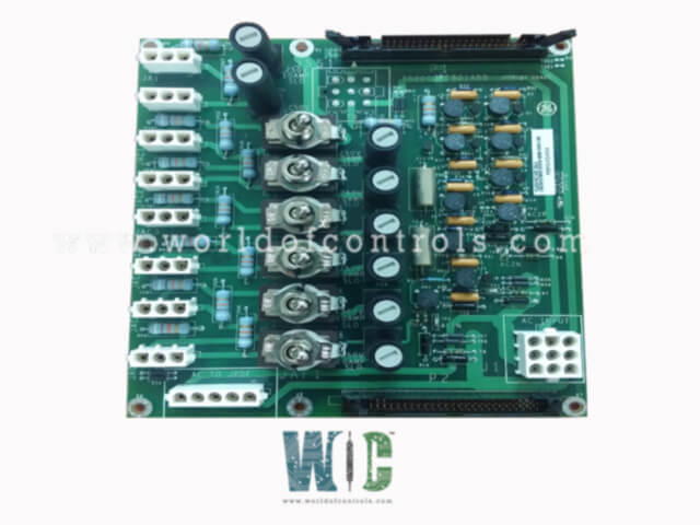
IS230JPDBG01 is a Power Distribution Module developed by GE. It is a part of Mark VIe control system. The AC Power Distribution Module is a component designed to condition, monitor, and distribute AC power within a system. It is equipped with essential features to ensure reliable and efficient power management. The module is designed to be compatible with the feedback signal P1/P2 connectors on JPDE, JPDF, JPDS, and JPDM, facilitating integration with a PPDA I/O pack. Additionally, connector JAF2 on the module is compatible with the AC input on the JPDF module, ensuring seamless connectivity between these components.
Board Installation
- The installation of the module begins with its secure mounting. This module should be base-mounted vertically on a metal back base within a cabinet designated for the Power Distribution Module (PDM). It is crucial to ensure that the module is firmly fastened to prevent any movement or vibrations that might affect its performance.
- Grounding the module is a safety step. A connection must be established between the sheet metal housing of the module and the system’s Protective Earth (PE). This grounding connection helps to prevent electrical noise and ensures the safe operation of the module by directing any stray electrical currents away from sensitive components.
- Connecting the input power involves two separate AC circuits. For the first AC circuit, connect the power lines to the terminals labeled AC1H (line) and AC1N (neutral). Similarly, for the second AC circuit, use the terminals labeled AC2H (line) and AC2N (neutral). It is essential that the neutral connections for both AC inputs are grounded to maintain system safety and integrity.
- Once the input power is connected, the output circuits need to be set up according to the system documentation. Proper connection of the output circuits ensures that power is distributed safely and efficiently to the intended components. Each output must be connected securely to match the system’s specifications, providing the necessary protection and distribution.
- For systems that include a PPDA power diagnostic I/O pack, a 50-pin ribbon cable is required to establish communication between the modules. This cable should be connected from the P1 connector on the module to the P2 connector on the board housing the PPDA I/O pack. If needed, the connection can pass through other core PDM boards using their P2 connectors, ensuring continuous signal integrity and effective monitoring.
Grounding
- Protective Earth (PE): The PE ground must be connected to a suitable earth connection, complying with all local standards and regulations. The grounding system should be robust enough to handle a current of 60 A for 60 seconds with no more than a 10-volt drop. This requirement ensures that the grounding system can safely dissipate fault currents without causing excessive voltage drops or overheating.
- Functional Earth (FE): The FE ground system is bonded to the PE ground system at a single point. This connection helps to establish a common reference ground while isolating functional elements from potential ground loops that could introduce noise or interfere with system operation.
- Grounding the JPDB Module: The module is grounded through its metal mounting supports, which are fastened to the underlying sheet metal of the module. This setup ensures that the metal switch bodies on the module are effectively grounded. The grounding also serves as a local reference point for creating feedback signals on connector P2. The module’s sheet metal is insulated from the surface on which it is mounted, allowing the definition of the JPDB ground to be independent of the mounting surface.
The WOC team is always available to help you with your Mark VIe requirements. For more information, please contact WOC.
Frequently Asked Questions
What is IS230JPDBG01?
It is a Power Distribution Module developed by GE under the Mark VIe series.
How do I connect the module to a JPDF (125 V DC) board?
Use the JAF1 connector to provide AC power to the JPDF board. Position the JPDF below the JPDB to minimize wiring lengths.
Where should the JPDS or JPDM holding the PPDA I/O pack be located?
Place the JPDS or JPDM at the top of the board arrangement. This setup allows ribbon cables to flow from one card to the next, starting at the top and entering the bottom of the next card.
