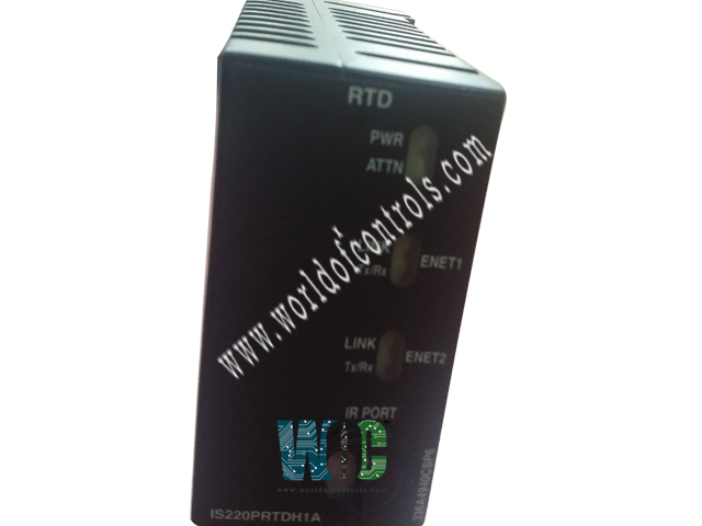
World Of Controls understands the criticality of your requirement and works towards reducing the lead time as much as possible.
IS220PRTDH1A, REV D - Resistance Temperature Device Input Module is available in stock which ships the same day.
IS220PRTDH1A, REV D - Resistance Temperature Device Input Module comes in UNUSED as well as REBUILT condition.
To avail our best deals for IS220PRTDH1A, REV D - Resistance Temperature Device Input Module, contact us and we will get back to you within 24 hours.
SPECIFICATIONS:
Part Number: IS220PRTDH1A, REV D
Manufacturer: General Electric
Series: Mark VIe
Product Type: Input Module
Number of Channels: 8
A/D Converter Resolution: 14-bit
Common Mode Voltage Range: ±5 Volts
Maximum Lead Resistance: 15 Ω maximum
Availability: In Stock
Country/Region of Manufacture: United States
Manual: GEH-6721L
FUNCTIONAL DESCRIPTION:
IS220PRTDH1A, REV D is a Resistance Temperature Device Input Module manufactured and designed by General Electric as part of the Mark VIe Series used in distributed control systems. The Resistance Temperature Device (RTD) Input (PRTD) pack electrically connects an RTD input terminal board with one or more I/O Ethernet networks. This pack includes a dedicated thermocouple acquisition board along with a processor board shared across all Mark VIe distributed I/O packs. It supports up to eight RTD inputs, while the TRTD terminal boards can handle up to sixteen RTD inputs. A DC-37 pin connector, which connects directly to the terminal board, and a three-pin power input provide input connectivity. For output, the pack is equipped with two RJ45 Ethernet connectors and visual diagnostics are provided through indicator LEDs.
COMPATIBILITY:
The RTD input terminal boards TRTDH1D, H2D, and the SRTD board are compatible with PRTDH1A, while the DIN-rail mounted DRTD board is not. Compatibility details are outlined in the table below.
INSTALLATION:
PROCESSOR BOARD OPERATION:
The acquisition board, which is specific to the function of the I/O pack or module, connects to the processor board. Upon applying input power, a soft-start circuit gradually increases the voltage available to the processor board. The processor reset is then deactivated, and the local power supply is sequentially activated. After completing self-tests, the processor loads application-specific code from flash memory for the particular I/O pack or module type. To confirm compatibility, the application code checks the board ID information for the acquisition and terminal boards. When a match is confirmed, the processor initiates Ethernet connections by requesting a network address.
The dynamic host configuration protocol (DHCP), which is the industry standard, and the terminal board's unique identifier are both used in the address request. Following Ethernet startup, the CPU runs the application, programs the on-board logic, and permits the acquisition board to start working.
DIAGNOSTICS:
WOC has the largest stock of OEM replacement parts for GE Distributed Control Systems. We can also repair your faulty boards and supply unused and rebuilt boards backed up with a warranty. Our team of experts is available round the clock to support your OEM needs. Our team of experts at WOC is happy to assist you with any of your automation requirements. For pricing and availability on parts and repairs, kindly contact our team by phone or email.
How many RTD inputs can the RTD Input Module support?
The RTD Input Module typically supports up to eight RTD inputs directly, while compatible terminal boards like the TRTD boards can support up to sixteen inputs.
Which terminal boards are compatible with the PRTD Module?
The TRTDH1D, TRTDH2D, and SRTD terminal boards are compatible with the PRTDH1A module. However, the DIN-rail-mounted DRTD board is not compatible.
What kind of isolation is used in the RTD Input Module?
The RTD Input Module uses galvanic isolation to protect the RTD input circuit, enhancing reliability and protecting the circuit from interference.